


Part of the Yanmar Repair Manuals.
All 712 pages of this Yanmar ViO57-6B Service Manual focus on one compact excavator: from engine crankshaft components to DPF removal and the full electronic control system. Inside: hydraulic circuit schematics with complete fluid routing, seat harness and cabin wiring diagrams broken down by reference number, a full error code list for the ECU, and step-by-step pressure adjustment procedures for relief valves and cut-off valves. Troubleshooting tables walk you through engine, turbocharger, cooling, lubrication, fuel, and electrical faults in one quick-reference section. Set the bleeder valve torque to 4.9–6.7 Nm; confirm filter valve opening pressure at 0.08–0.12 MPa. Factory numbers only. Your excavator is down and every idle hour costs money. Bookmarked and keyword-searchable; open it on your tablet at the machine and start wrenching.
What's Inside This Yanmar ViO57-6B Manual
| System | Pages | Key Topics |
|---|---|---|
| Specifications & Maintenance Schedule | 15-33 | Dimensions, Oil Pressure Specifications, Periodic Inspection Schedule, Hydraulic Circuit, Engine, Chassis, Electrical Equipment, Fuel/Lube Oil/Grease Recommended, Quantity Prescribed |
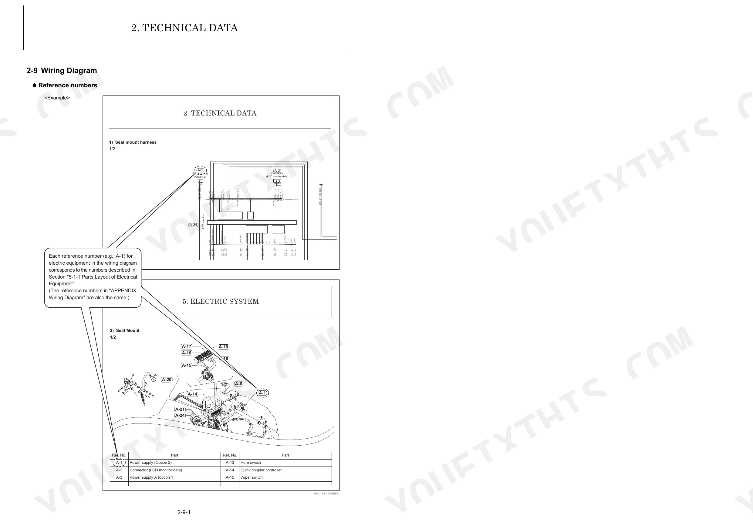
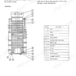
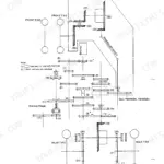
| Hydraulic & Wiring Diagrams | 34-39 | Hydraulic Circuit Schematic, Component Identification, Flow Path Routing, Pressure Zones, Wiring Diagram, Seat Mount Harness, Cabin, Air Conditioner Spec. |
| Pressure Adjustment | 40-76 | Relief Valves, Swing Brake Valve, Cut-Off Valve, Adjustment Procedure |
| Safety | 77-90 | Safety Precautions, High Pressure Hazard, Scald Hazard, Explosion Hazard, Crush Hazard |
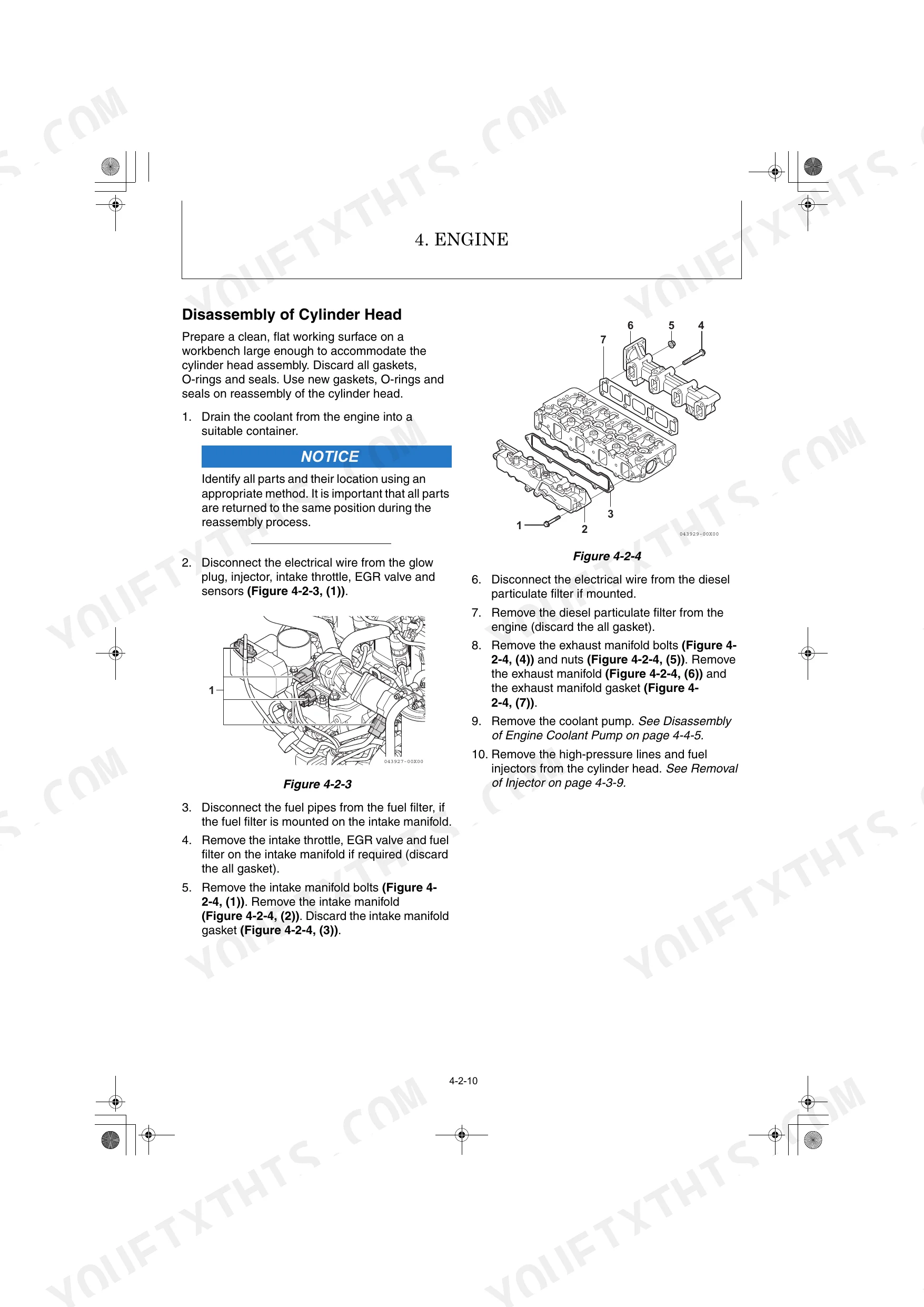
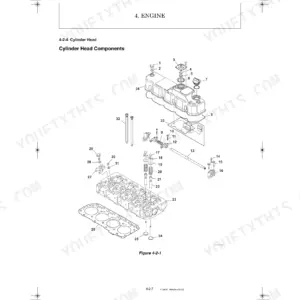
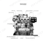
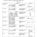
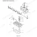
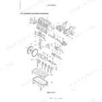
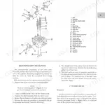
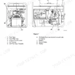
| Engine | 91-148 | Special Service Tools, Measuring Instruments, Cylinder Head, Crankshaft and Camshaft Components |
| Fuel System | 149-161 | System Structure, Fuel System Specifications, Fuel System Diagram, Fuel System Components |
| Cooling & Lubrication System | 162-175 | Cooling System Diagram, Engine Coolant Pump Components, Engine Coolant System Check, Lubrication System Diagram, Engine Oil Pressure Check, Oil Pump Components |
| Turbocharger, Starter Motor & Alternator | 176-210 | Turbocharger Specifications, Turbocharger Components, Washing Procedure, Starter Motor Specifications, Starter Motor Components, Alternator Specifications, Alternator Wiring Diagram |
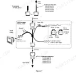
| Electronic Control System & Troubleshooting | 211-260 | Diesel Particulate Filter (DPF) Removal/Reattachment, Sensor Installation Positions, Electric Wiring Harness Layout, Connector Locations, Compression Inspection Procedures, Quick Reference Troubleshooting Table, Failure Diagnostic List |
| Electric Equipment & Engine ECU | 261-297 | LCD Monitor and Alarm Systems, Accelerator Dial, Accelerator Sensor, Ignition Circuit, Key Switch Operation, Engine ECU Pin Layout, ECU Fault Codes, Error Descriptions |
| Hydraulic Pump, Control Valve & PTO Solenoid Valve | 298-533 | Hydraulic Pump Specifications, Control Valve Specifications, Disassembly and Reassembly Procedure, Proportional Solenoid Valve for P.T.O, Theory of Operation, Troubleshooting |
| Cabin & Air Conditioner | 534-712 | Removal and Reinstallation of Cabin, Glass and Door Installation, Air Conditioner Removal, Compressor Removal, Air Conditioner Specifications |
Quick Reference Specifications
| Specification | Value | Page |
|---|---|---|
| Bleeder valve tightening torque | 4.9 Nm to 6.7 Nm | p. 13 |
| LO filter filtration area | 1160 cm² | p. 23 |
| Filter valve opening pressure | 0.08 MPa to 0.12 MPa | p. 23 |
| Air cleaner filtration area | 2.37 cm² | p. 24 |
| Coolant hose replacement interval | Every 1000h / Every year | p. 31 |
| Rubber crawler wear limit (A) | 5 mm | p. 55 |
| Sprocket wear limit (A) | 10 mm | p. 49 |
| Hydraulic hose tightening torque (parallel pipe thread G (PF) 1/8) | 12 N·m to 14 N·m | p. 67 |
| System relief set pressure P1 (Piston pump P2) | 24.5 MPa at 30 | p. 68 |
| System relief set pressure P2 (Piston pump P1) | 24.5 MPa at 30 | p. 68 |
| Operating temperature of water temperature alarm switch | 107 °C to 113 °C | p. 24 |
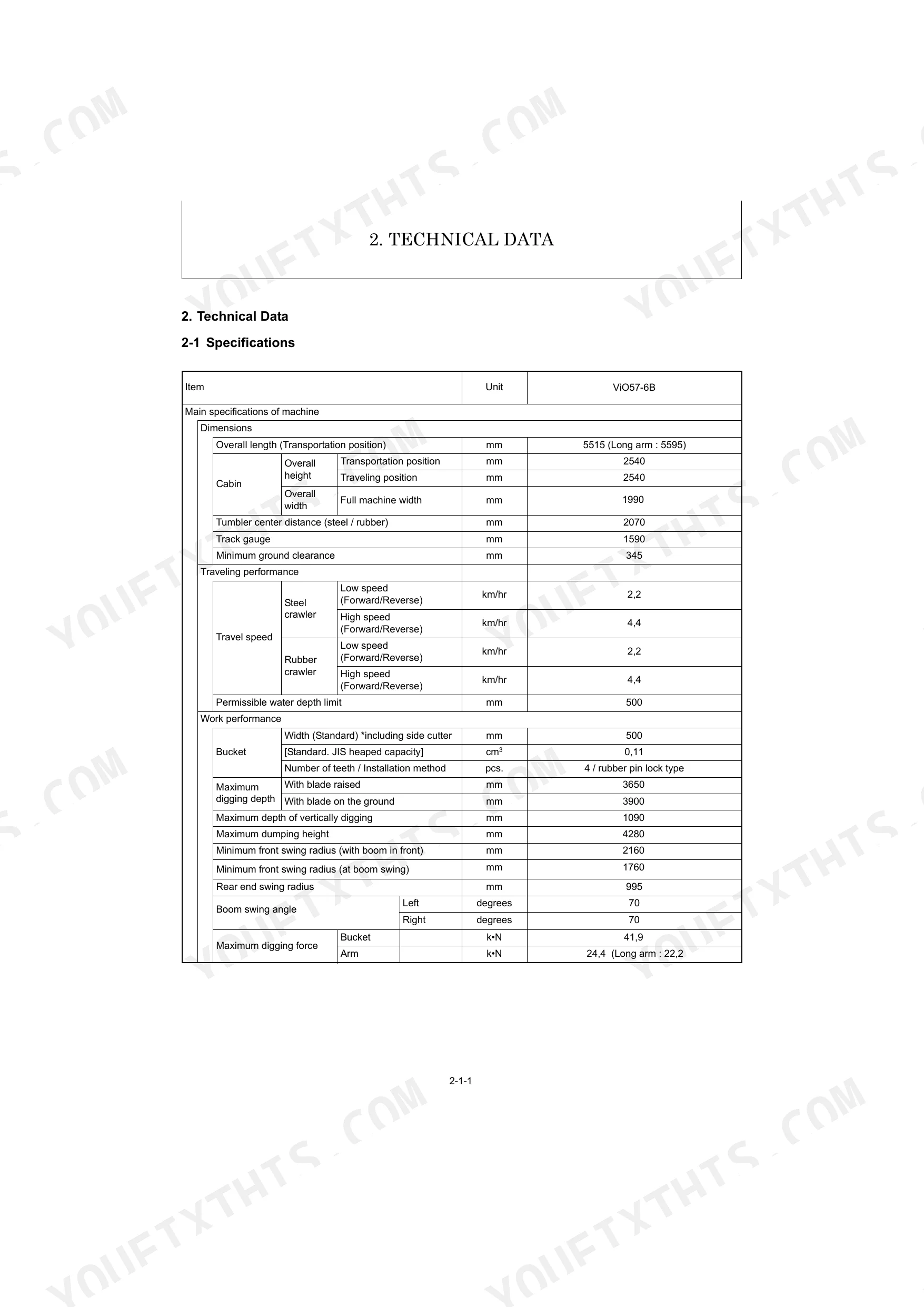
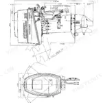
| Overall length (Transportation position) | 5515 mm | p. 18 |
Yanmar ViO57-6B Common Problems This Manual Covers
Yanmar ViO57-6B engine runs roughly, loses power, or stalls shortly after cold startup
Drain the fuel/water separator daily before starting. Water contamination is the top cause of rough running and stalling on this machine. Inspect the fuel system components starting on page 149 and replace the separator element if water or sediment is present. The diesel tank capacity is 66.0 L; verify no debris entered during the last refill.
Manual Section: 4-3 Fuel System p. 149Hydraulic functions suddenly slow down, boom won't lift to full height, or bucket curls weakly
Check hydraulic oil level first. Tank capacity is 42 L; top up using fluid specified on page 16. Measure system relief pressure at the P1 and P2 circuits. Set pressure should reach 24.5 MPa (page 68). If pressure reads low, consult the hydraulic circuit schematic on page 34 to trace any leak path before disassembly.
Manual Section: 3-8 Pressure Adjustment p. 68Coolant temperature warning triggers mid-cycle, engine temperature gauge climbs into the red zone
Verify coolant level. Radiator capacity is 7.0 L; top up if low. Inspect hoses for cracking or soft spots; replace every 1000 hours or annually (page 31). The water temperature alarm switch triggers at 107°C to 113°C. If the gauge hits that range, shut down immediately and run the cooling system diagnosis on page 162.
Manual Section: 4-4 Cooling System p. 162Track pulls to one side during travel, or rubber crawler shows excessive wear on one edge
Inspect the rubber crawler. The wear limit (dimension A) is 5 mm (page 55); replace before reaching it. Check sprocket teeth against the 10 mm wear limit on page 49. When reinstalling, torque sprocket bolts to 127 N·m to 149 N·m with Loctite 262 per page 60. One-sided wear usually points to a misaligned idler or uneven tension.
Manual Section: 3-8 Pressure Adjustment p. 55Engine warning light stays on after DPF service, or monitor shows an active regeneration fault
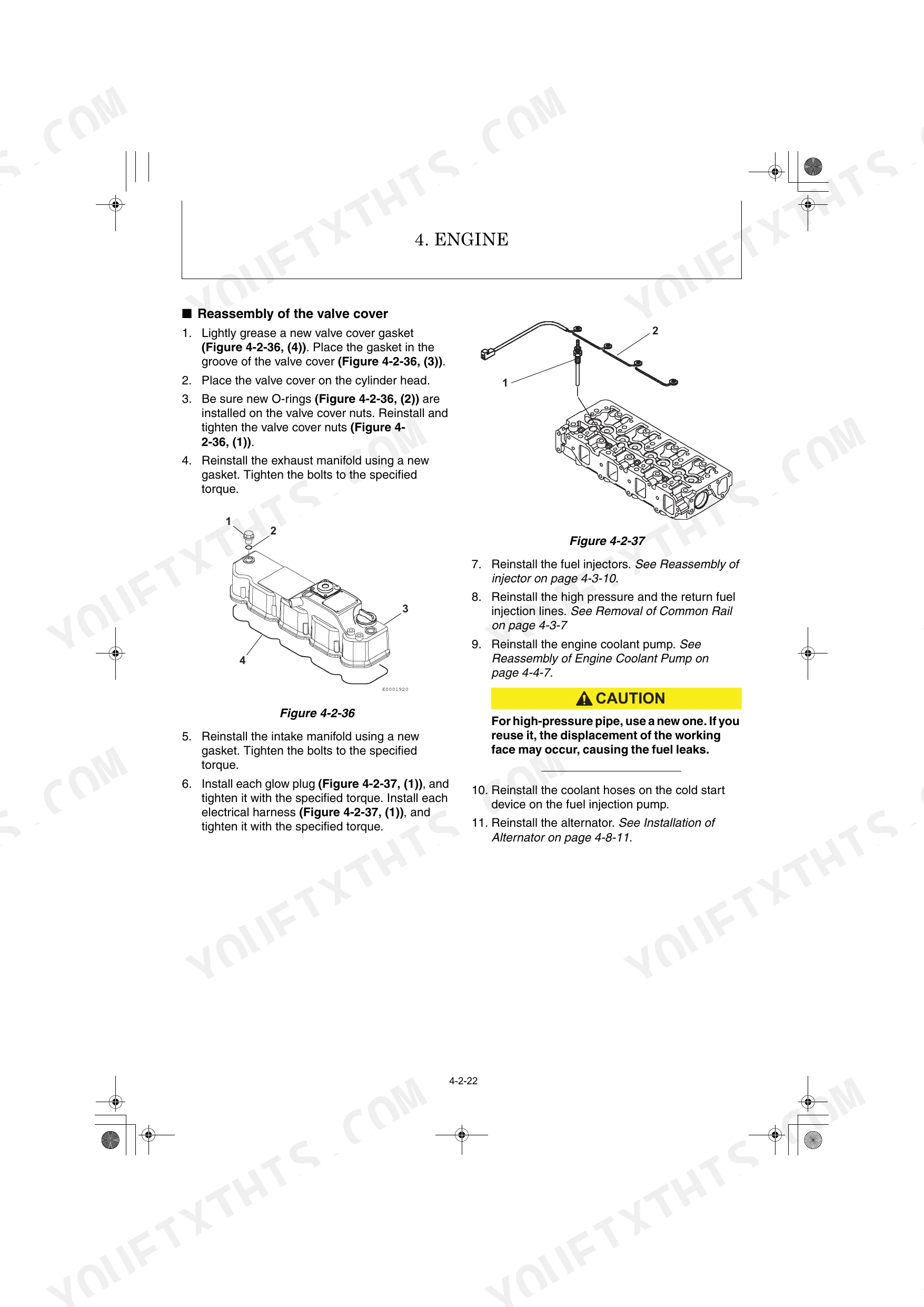
Follow the DPF regeneration processing procedures after parts replacement on page 211. Check sensor connections at the positions shown in the electronic control system section. Look up the specific fault code in the error code list on page 284. If injectors were disturbed during service, retorque the bolts to 24.4 to 28.4 N·m per page 65.
Manual Section: 4-9 Electronic Control System p. 211Frequently Asked Questions
What are the torque specs for the Yanmar ViO57-6B engine?
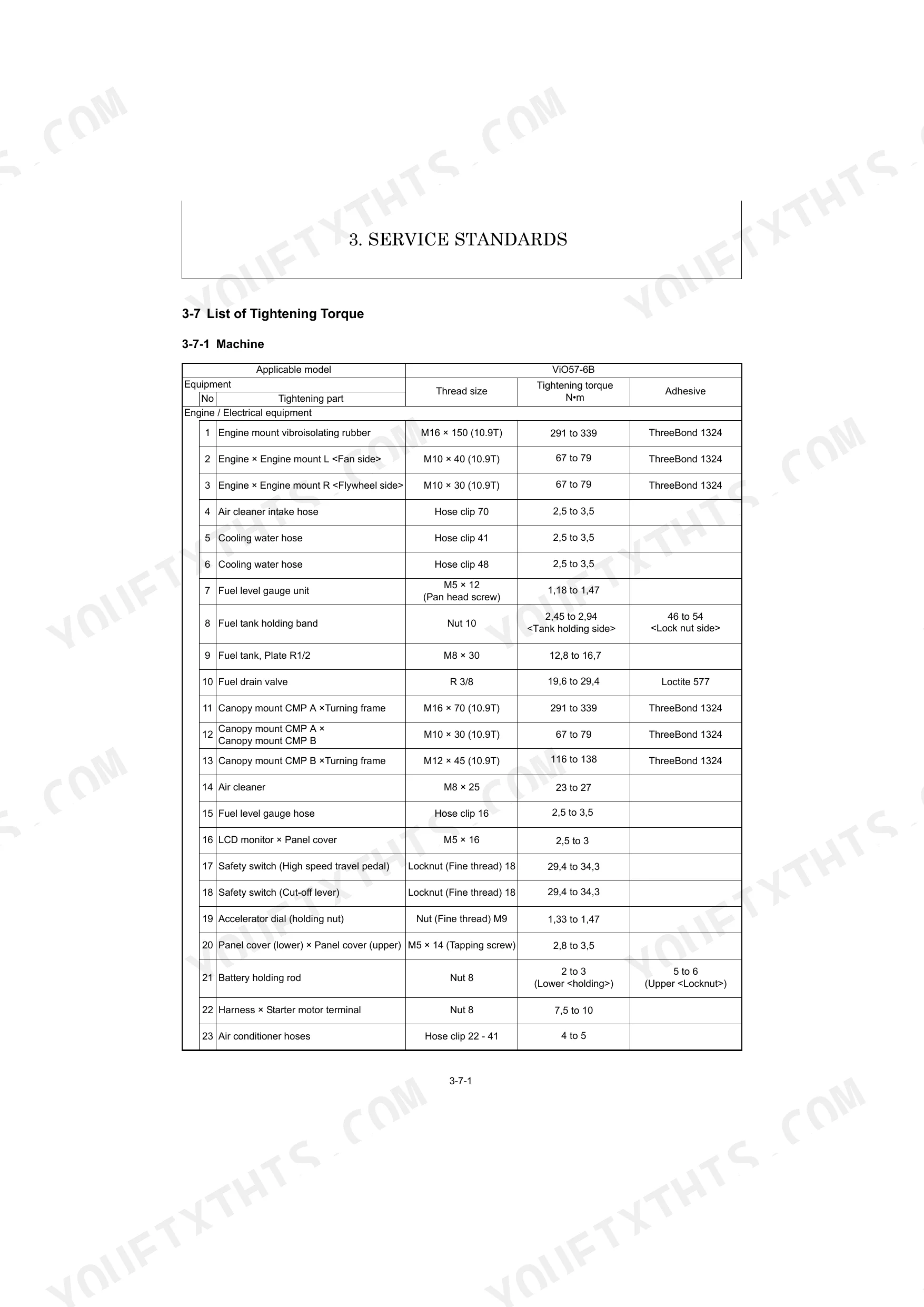
The Yanmar ViO57-6B engine has various torque specifications for major bolts and nuts. For instance, cylinder head bolts (M10 X 1.25) require 85.3 to 91.1 N·m, connecting rod bolts (M9 X 1.0) require 44.1 to 49.0 N·m, and flywheel bolts (M10 X 1.25) require 83.3 to 88.2 N·m. Many of these also require lubricating oil during tightening. p. 64
How to reset error codes on Yanmar ViO57-6B?
To reset error codes on the Yanmar ViO57-6B, if the fault indicator lamp comes on, you should stop the engine immediately and contact your local YANMAR dealer. A genuine YANMAR diagnosis tool, SMARTASSIST DIRECT (SA-D), is required to connect to the engine for fault diagnosis, which allows clearing error information from the “Defect History” by pressing the “All Clear” button. For many error codes, a basic check involves turning the starter switch to the "OFF" position and then to the "ON" position to see if the code persists. p. 233
What are the common error codes for Yanmar ViO57-6B?
The Yanmar ViO57-6B manual lists various error codes. Some common examples include: 00 000051.03 for Intake throttle position sensor malfunction (High voltage), 00 000091.03 for Accelerator sensor malfunction (High voltage), 00 000100.01 for Low engine oil pressure alarm, and 00 000110.00 for Abnormally-high coolant temperature (Overheating). p. 284
How to reset the Yanmar ViO57-6B monitoring system after an engine fault?
After an engine fault, if the fault indicator lamp comes on, you should stop the engine immediately and contact your local YANMAR dealer. A genuine YANMAR diagnosis tool, SMARTASSIST DIRECT (SA-D), is required to connect to the engine for fault diagnosis and to review detailed fault information. p. 233
What format is this manual in?
This is a 712-page searchable PDF ready for immediate download. Works on any device, so pull it up on your phone while you're under the hood. No shipping, no waiting.
Can I print this manual?
Absolutely. No DRM or copy protection. Print the whole manual or just the pages you need. Any home or office printer works.
Does this Yanmar ViO57-6B manual include hydraulic schematics?
Yes. The manual includes hydraulic circuit diagrams, system schematics, and component specifications with pressure ratings.
Reviews
There are no reviews yet.