Part of the Yanmar Operator Manuals.
Air in the fuel system will keep a 4JH cranking dead while the tide goes out, and the 48 pages of this Yanmar operation manual exist to get you past exactly that kind of stoppage: the bleeding procedure, the service intervals, and a troubleshooting chart that starts at the fuel shut off valve and works outward. It covers the 4JHE, 4JH-TE, 4JH-HTE, and 4JH-DTE marine diesel engines under Yanmar publication 129470-2E, in English.
Inside are the factory procedures for installation and engine bed preparation, fuel and lubricating oil selection, first start on a new engine, daily operation, storage and recommissioning, and periodical inspection of the fuel, lube oil, cooling, and electrical systems, plus piping and wiring diagrams for every variant.
When the engine is apart on the bench, page 29 carries the numbers that matter before reassembly: valve lash, injection timing, injector pop pressure, and the cylinder head torque sequence figures.
Complete the set for your 4JHE, 4JH-TE, 4JH-HTE…
What's Inside This Manual
| System | Pages | Key Topics |
|---|---|---|
| Specifications | 6 | 1-1.Engine Specafications, 1-2.Marine Gear Spacifications |
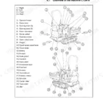
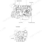
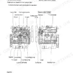
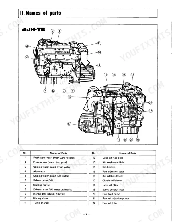
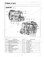
| Names of Parts | 7-8 | Fresh Water Tank, Pressure Cap, Cooling Water Pump, Alternator, Exhaust Manifold, Turbo-Charger |
| Engine Installation | 9-14 | 3-1.Inspection After Unpacking, 3-2.Preparation of the Engine Foundation Plate, 3-3.Engine Installation, 3-4.Propeller, Propelleer Shaft, 3-5.Cooling Water Supply Device |
| After Launching | 15 | |
| V.Fuel and Lubricating Oil | 16-17 | 5-1.Selection and Handling of Fuel Oil, 5-2.Selection of Lubricating Oil |
| Starting the New Engine for the First Time | 18-21 | 6-1.Supply of Fuel Oil, 6-2.Supply of Lubricating Oil, 6-3.Bleeding Air From the Fuel System, 6-4.External Inapection, 6-5.Checking the Instrument Panel Alarm System, 6-6.Tuening |
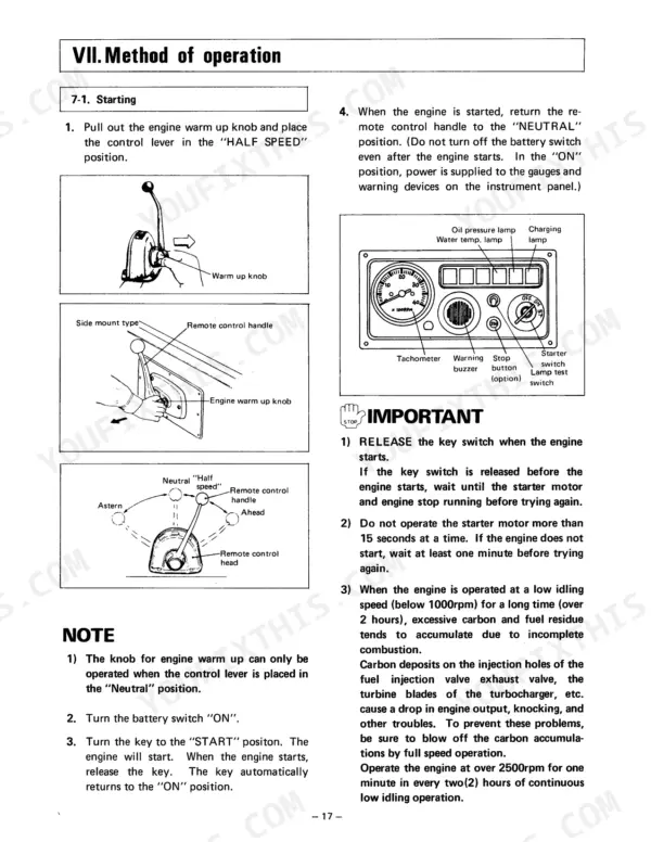
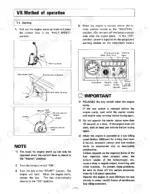
| Method of Operation | 22-26 | 7-1.Starting, 7-2.Cautions After Starting the Engine, 7-3.Cautions During Operation, 7-4.Stopping |
| Storage | 27 | 8-1.Storing, 8-2.Removing Engine From Storage |
| Periodical Inspection and Maintenance | 28-36 | 9-1.Fuel Oil System, 9-2.Lubricating Oil System, 9-3.Cooling Water System, 9-4.Inspection of Engine Body, 9-5.Washing the Air Intake Silencer Element, 9-6.Electrical Equipment |
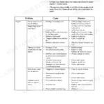
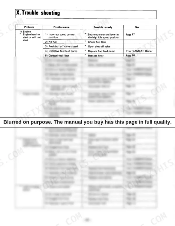
| Trouble Shooting | 37-40 | Incorrect Speed Control Position, No Fuel, Fuel Shut Off Valve Closed, Defective Fuel Feed Pump, Clogged Fuel Filter, Air in Fuel System |
| Fuel Oil, Lubricating Oil and Cooling Water Piping Diagram | 41-42 | 11-1.4JH-TE, 4JH-Hte, 4JH-Dte, 11-2.4JHE |
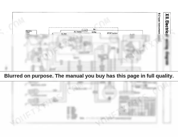
| Electrical Wiring Diagram | 43-45 | Battery, Air Heater, Stop Button, Key Switch, Alternator, Water Temp. Switch |
| Optional Device | 46-47 | Air Heater, Electric Type Engine Stopping Device, Solenoid, Engine Stop Lever, Intake Manifold, Relay |
Quick Reference Specifications
| Specification | Value | Page |
|---|---|---|
| All Models | ||
| Cylinder head tightening torque (M10) | 8 ± 0.5 kg-m | p. 29 |
| Alternator belt tension (with 10kg thumb force) | 10mm | p. 29 |
| Fuel injection pressure | 200±5kg/cm² | p. 29 |
| Fuel injection timing | bTDC12°±1° | p. 29 |
| Fuel filter replacement interval | Every 300 hours | p. 28 |
| Cooling water pipe inside diameter | 25.4 mm | p. 11 |
| Impeller check/replacement interval (sea water pump) | Every 600 hrs | p. 28 |
| 4JH-TE, 4JH-HTE, 4JH-DTE | ||
| Compressor cleaning interval (standard) | Every 150 hours | p. 36 |
| Compressor cleaning interval (with fresh water) | Every 50 hrs | p. 36 |
| 4JHE | ||
| Continuous rating output (DIN 6270A) | 40 hp/3500 rpm | p. 6 |
| 4JHE, 4JH-TE, 4JH-HTE | ||
| Engine Lube oil capacity (Crank case) (4JHE, 4JH-TE, 4JH-HTE) | 6.5ℓ | p. 20 |
| 4JH-DT(B)E | ||
| Engine Lube oil capacity (Crank case), 4JH-DT(B)E | 8.0ℓ | p. 6 |