


Part of the Yanmar Repair Manuals.
Every detail of your instrument panel is covered in this 20-page Yanmar yd25 operation manual pdf (OEM #164100-29010), built specifically for the YD25, JH, and 4LV units. You get complete harness installation guides, detailed wiring diagrams, and dimensional drawings to ensure a perfect fit in the console. Open the active alarms section to decode DTC error codes directly from the LCD display, or review the system setup procedures to link the engine model correctly on the first power-up. Verify your supply voltage reads between 8 and 16 VDC, and confirm you are running a 3A maximum fuse on the accessory power line before firing up the system. Stop staring at a blank screen wondering what that flashing alarm means. Grab this bookmarked digital file, pull it up on your tablet, and get the engine monitoring system back online today.
What's Inside This Yanmar YD25 Manual
| System | Pages | Key Topics |
|---|---|---|
| Overview | 4 | Lcd Display, Power, Start/Stop, Select, Enter |
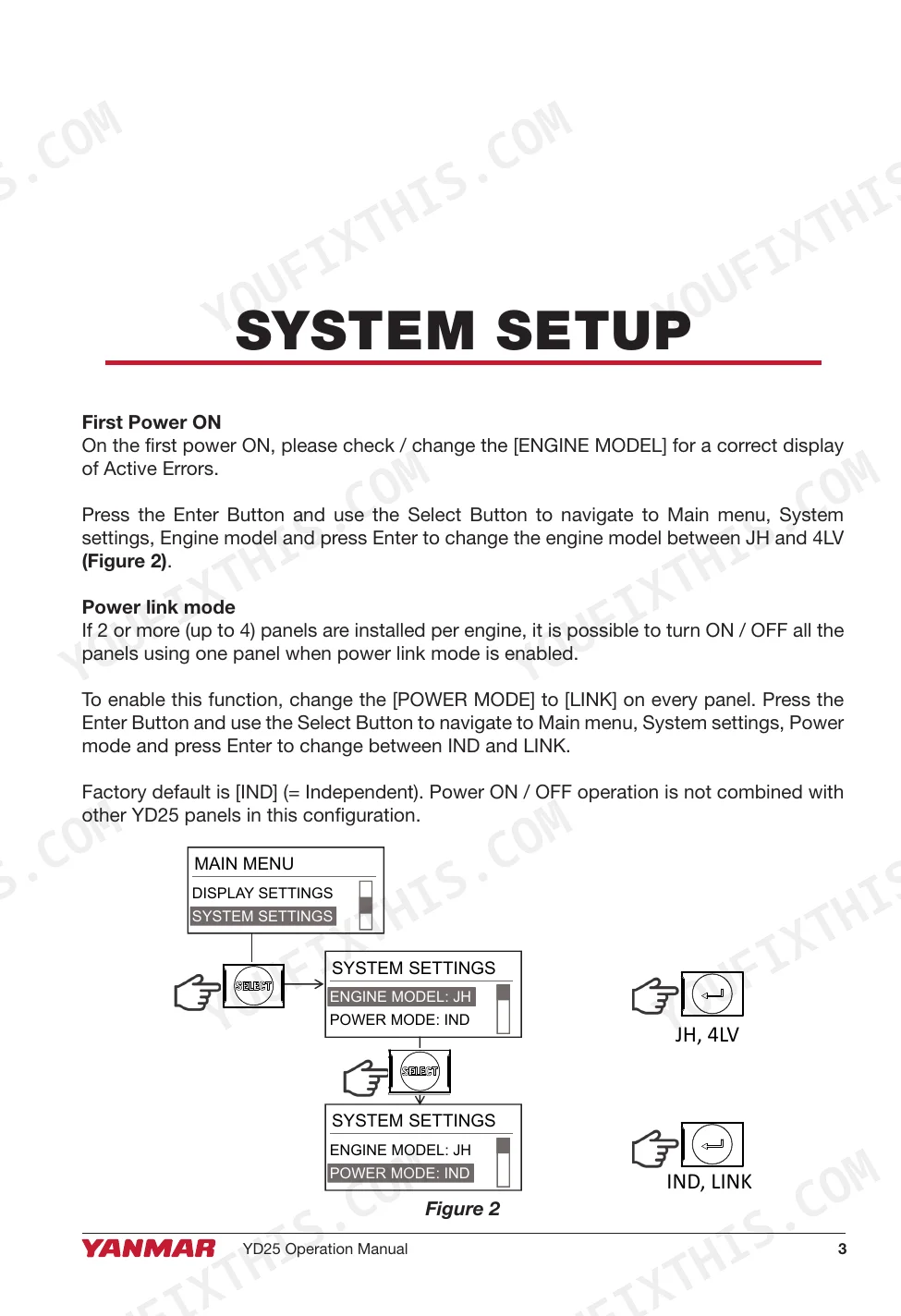
| System Setup | 5 | First Power on, Power Link Mode, Engine Model, Power Mode, Ind, Link |
| Operation | 6-7 | Power on, Power Off, Engine Start, Engine Stop, Engine Monitoring Screens, Screen Pages |
| Main Menu | 8-11 | Active Alarms, Active Errors, Display Settings, System Settings, Error Code (Dtc), Fuel Sensor |
| Menu Structure | 12 | Main Menu, Active Alarms, Active Errors, Display Settings, System Settings, Engine Model |
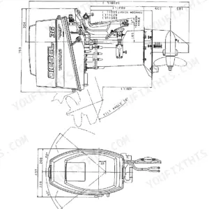
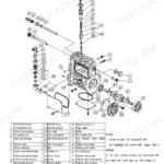
| Dimensional Drawings | 13 | - |
| Technical Specifications | 14 | Electrical, Supply Voltage, Power Consumption, Lcd Display, Display Resolution, Waterproof Rating |
| Harness Installation | 15-20 | Terminator, YD25 Harness, Accessory Power, Fuse, Mating Connector, Fuel Tank Sensor |
Quick Reference Specifications
| Specification | Value | Page |
|---|---|---|
| Product weight | 115 g | p. 14 |
| Accessory Power Fuse | 3A Max | p. 15 |
| Accessory Power Voltage | 12VDC | p. 15 |
| Supply voltage (min) | 8 VDC | p. 14 |
| Supply voltage (max) | 16 VDC | p. 14 |
| Power consumption | 100 mA | p. 14 |
| Display Size | 2.5" diagonal | p. 14 |
| Display Resolution | 164 X 64 pixels | p. 14 |
| Brightness | 100 mcd | p. 14 |
| Operating temperature (min) | -10°C | p. 14 |
| Operating temperature (max) | +65°C | p. 14 |
| Fuse rating | 3A | p. 15 |
Yanmar YD25 Common Problems This Manual Covers
Yanmar YD25 instrument panel goes completely dead with no buzzer, lights, or tachometer output
Check the main power connections to the display. Verify the supply voltage measures between 8 VDC and 16 VDC across the harness. Inspect the wiring diagram on page 15 to trace the earth connection. Clean the ground terminals and replace any damaged connectors.
Manual Section: Harness Installation p. 15Engine hour display stops showing correctly or the LCD screen loses readability over time
Inspect the instrument panel for heat damage if operated outside the -10°C to +65°C limit. Review the technical specifications on page 14. Replace the entire 115 g display assembly if the internal LCD module fails, as the internal hour counter memory cannot be rebuilt.
Manual Section: Technical Specifications p. 14Display shows strange or intermittent behavior after connecting external devices to the wiring harness
Disconnect any recently installed add-on hardware from the harness. Check the wiring diagram on page 15 and confirm the accessory circuit uses a maximum 3A fuse. Inspect the DT06-2S (TE) mating connectors for bent pins or improper splices that drain the required 100 mA power.
Manual Section: Harness Installation p. 15Networked multifunction display shows no engine data and sounds a continuous steady alarm
Access the active alarms menu on page 8 to view specific error codes. Verify the communication link between the engine and panel receives steady 12VDC power. Check the system overview diagram on page 12 for correct network integration and clear any stored fault codes.
Manual Section: Main Menu p. 8Frequently Asked Questions
How can I view active error codes and their details on the YD25 Instrument Panel?
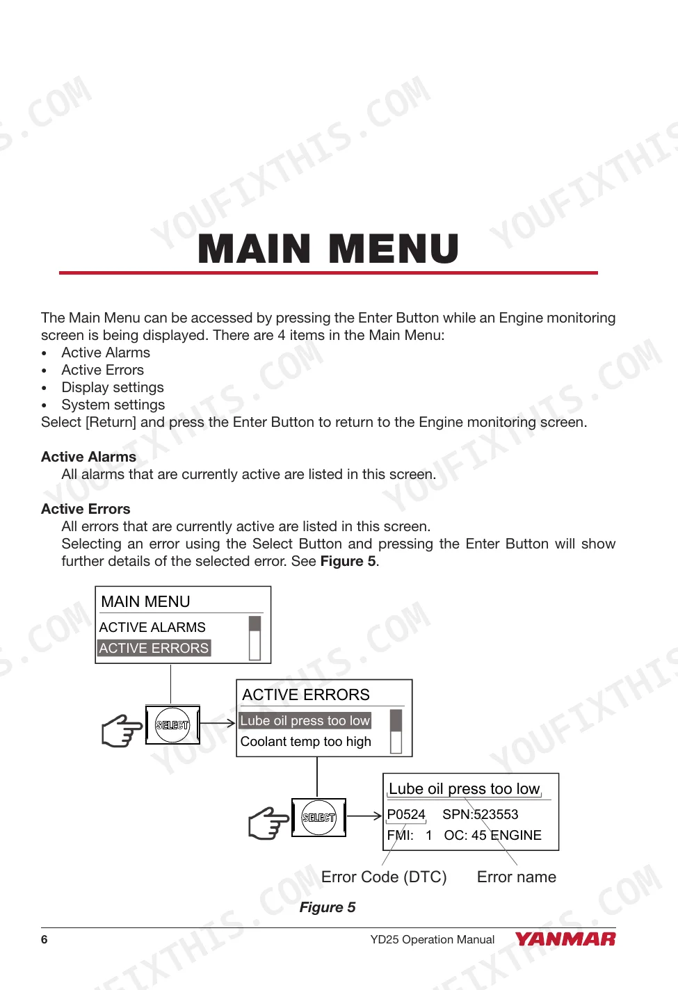
To view active error codes, press the Enter Button to access the Main Menu, then go to "Active Errors" using the Select Button. Selecting an error and pressing Enter again will display further details such as the Error code (DTC), SPN, FMI, Occurrence, and Error source, as shown in Figure 5 on page 8. p. 8
What are the display and physical specifications for the YD25 Instrument Panel?
The YD25 Instrument Panel features a 2.5" diagonal, 164 x 64 pixel transflective monochrome LCD with 100 mcd brightness. Physically, it measures 82.5 mm (3.24") in width, 66 mm (2.6") in height, and 36.8 mm (1.45") in depth. The product weighs 115 g. p. 13
What are the electrical specifications for the YD25 Instrument Panel, including supply voltage and power consumption?
The YD25 Instrument Panel operates on a supply voltage of 12VDC (8~16 VDC) and has a power consumption of 100 mA (@ No output load). These specifications are crucial for proper installation and operation of the panel. p. 14
What is the waterproof rating for the YD25 Instrument Panel?
The YD25 Instrument Panel has a waterproof rating of IPX6 and IPX7 for the front, and IPX7 for the back. This ensures durability and protection against water ingress in marine environments. p. 14
How will I receive this Yanmar YD25 Operation Manual?
This is a 20-page searchable PDF ready for immediate download. Works on any device, so pull it up on your phone while you're under the hood. No shipping, no waiting.
Is this Yanmar YD25 Operation Manual printable?
No copy protection at all. The PDF is DRM-free, so print whatever sections you need to take to the shop. Standard letter or A4 paper works.
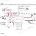
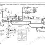
Can I find wiring schematics in this Yanmar YD25 manual?
Yes, this Yanmar YD25 Operation Manual includes a wiring diagram for the electrical system.


Reviews
There are no reviews yet.