


Part of the Case IH Repair Manuals.
All 767 pages of this Case IH JX55T, JX75T Service Manual (OEM #47899737) are built around one job: factory-level repair of your tractors. Inside, you get hydraulic schematics with full fluid routing through the fixed displacement pump, main control valve, and remote control valves, plus wiring diagrams tracing every harness, connector, alternator circuit, and warning indicator in the electrical system. A deep troubleshooting section, exploded views of the front and rear axle assemblies, PTO drive shaft, planetary finals, and a full clearances chapter round out the coverage. Torque the cylinder head bolts to 40 N·m, then add 125–135° and a second 135–145° pass; pull the main bearing cap figure at 80 N·m plus 90°. Your machine is down. Get the factory answer on the first try, not a forum guess. Bookmarked and keyword-searchable; pull it up on any device and start wrenching.
What's Inside This Case IH JX55T–JX75T Manual
| System | Pages | Key Topics |
|---|---|---|
| Introduction | 7-22 | Foreword, Safety Rules |
| Engine - 10 | 23-218 | Engine and Crankcase, Pan and Covers, Valve Drive and Gears, Cylinder Heads, Connecting Rods and Pistons, Crankshaft and Flywheel, Balancer and Damper, Fuel Injection System |
| Clutch - 18 | 219-250 | Clutch and Components |
| Transmission - 21 | 251-314 | Mechanical Transmission, Mechanical Transmission Internal Components, Gearbox External Controls, Gearbox Internal Components |
| Four-Wheel Drive (4WD) System - 23 | 315-330 | Drive Shaft |
| Front Axle System - 25 | 331-394 | Non-Powered Front Axle, Powered Front Axle, Front Bevel Gear Set and Differential, Final Drive Hub, Steering Knuckles, And Shafts |
| Rear Axle System - 27 | 395-448 | Powered Rear Axle, Rear Bevel Gear Set and Differential, Planetary and Final Drives |
| Power Take-Off (PTO) - 31 | 449-470 | Rear Mechanical Control, Power Take-Off Drive Shaft |
| Brakes and Controls - 33 | 471-498 | Mechanical Service Brakes, Parking Brake or Parking Lock |
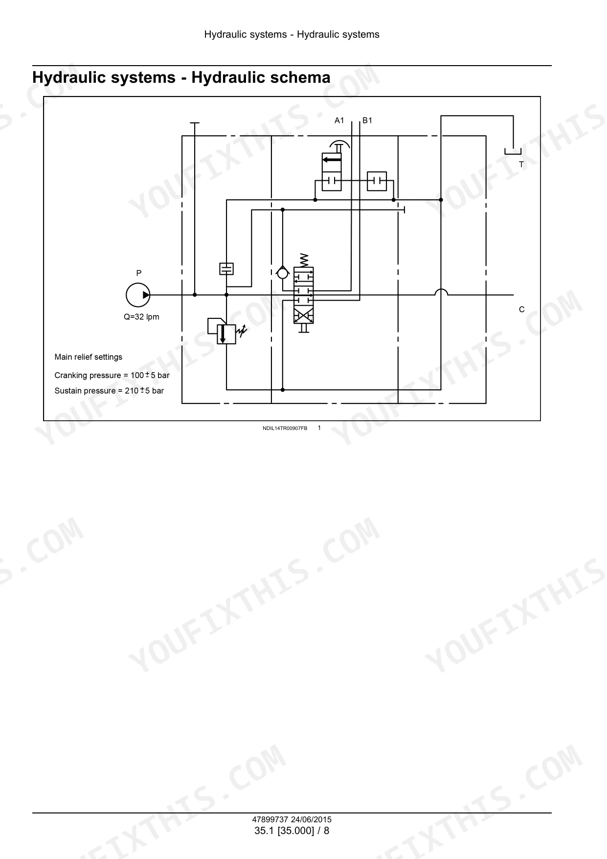
| Hydraulic Systems - 35 | 499-604 | Hydraulic Systems, Fixed Displacement Pump, Main Control Valve, Remote Control Valves, Main Lift System |
| Steering - 41 | 605-676 | Steering Control, Hydraulic Control Components, Cylinders |
| Wheels - 44 | 677-684 | Front Wheels |
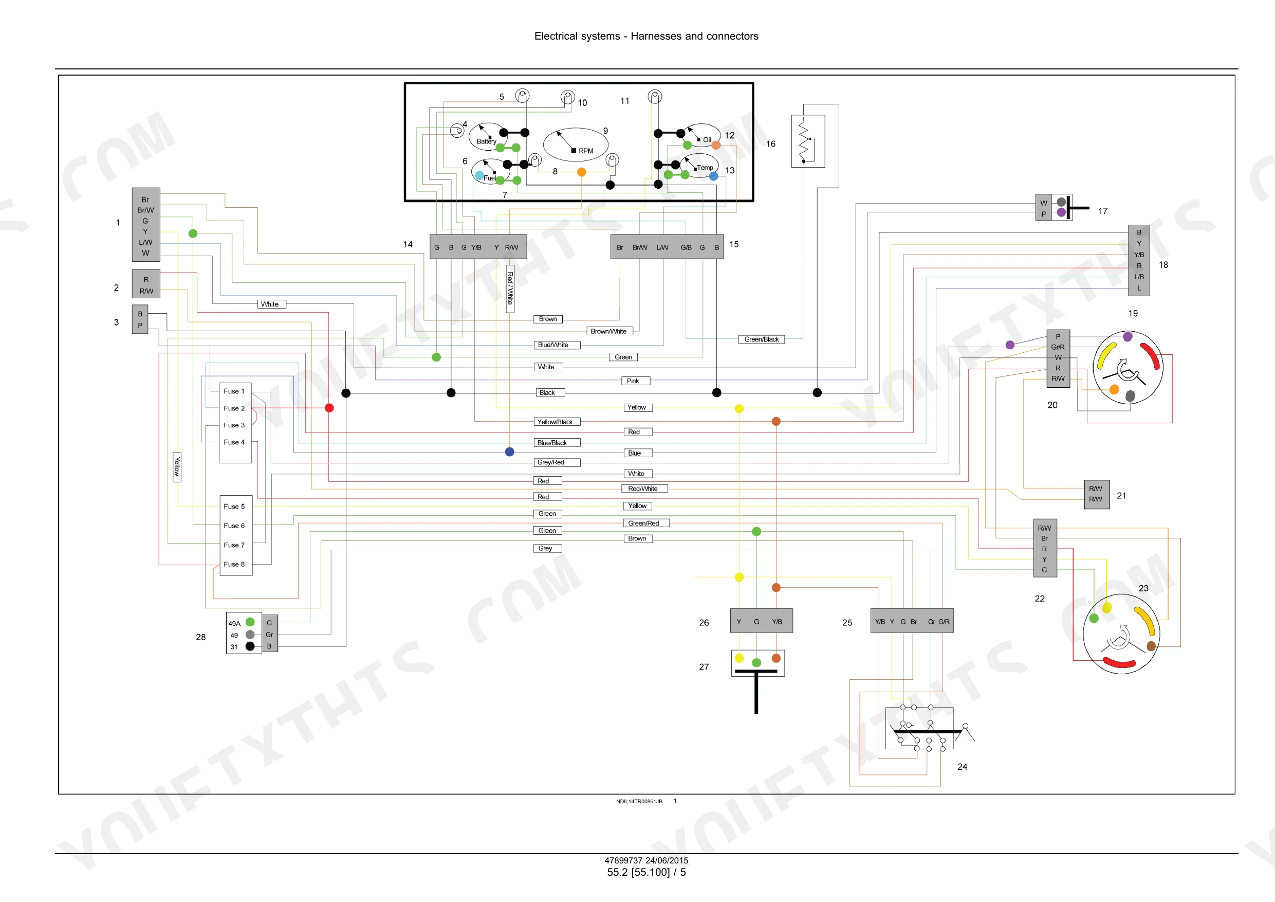
| Electrical Systems - 55 | 685-765 | Electrical System, Harnesses and Connectors, Engine Starting System, Alternator, Battery, External Lighting, Warning Indicators, Alarms |
Quick Reference Specifications
| Specification | Value | Page |
|---|---|---|
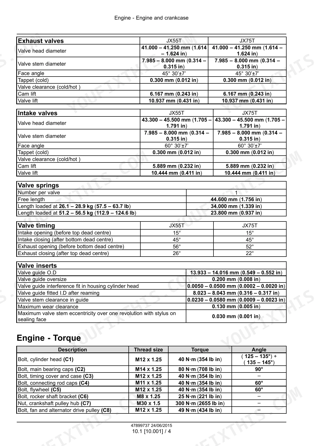
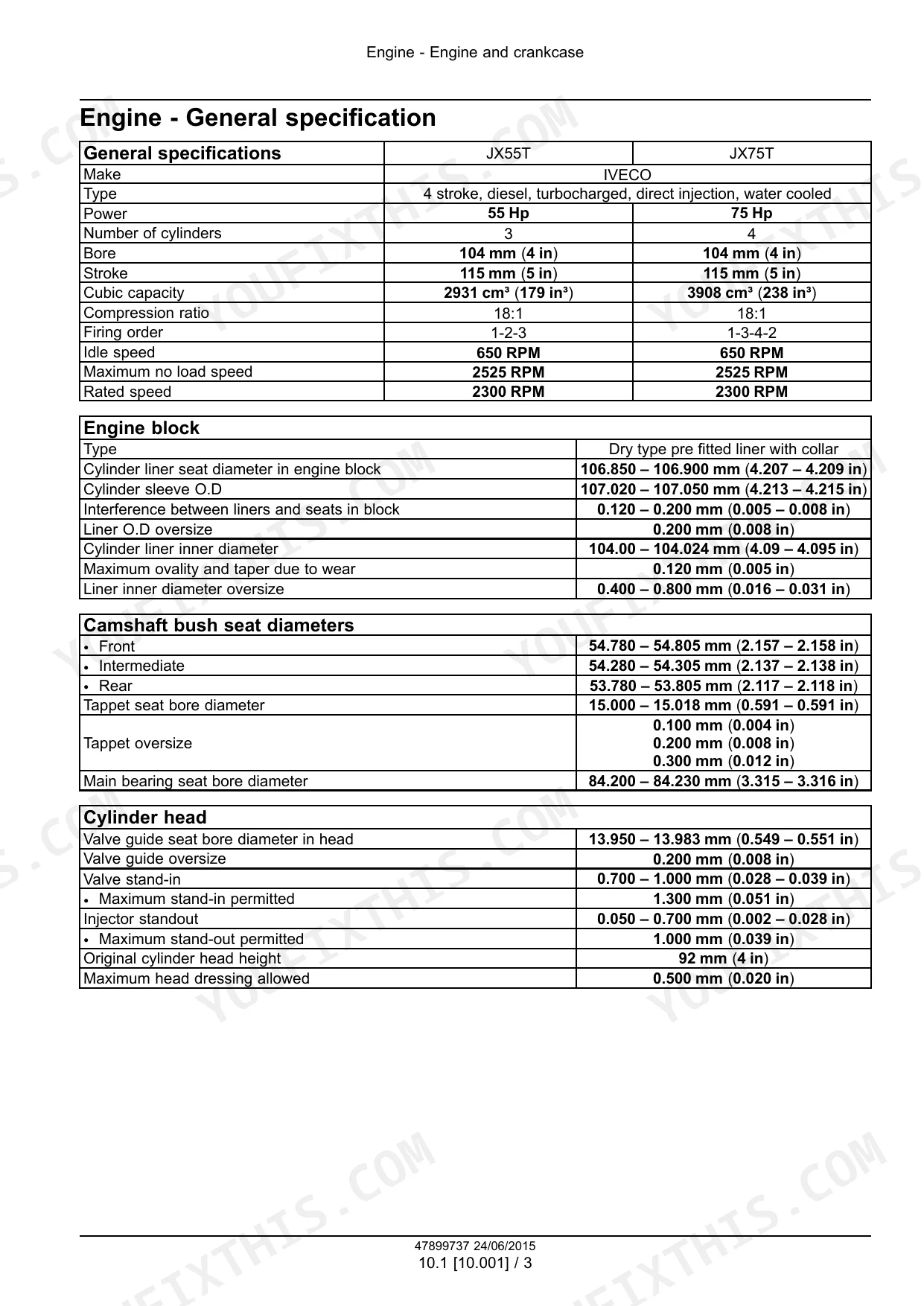
| Bolt, cylinder head (C1) torque | 40 N·m (354 lb in) + (125 – 135°) + (135 – 145°) | p. 27 |
| Bolt, main bearing caps (C2) torque | 80 N·m (708 lb in) + 90° | p. 27 |
| Injectors Make | MICO BOSCH | p. 138 |
| Nozzle holder | KBEL 83S352 260 (apa) | p. 138 |
| Pump gear journal dia | 17.400 – 17.418 mm (0.685 – 0.686 in) | p. 512 |
| Journal housing bore dia. in bearing | 17.450 – 17.470 mm (0.687 – 0.688 in) | p. 512 |
| Transmission plate thickness | 8.800 – 9.600 mm (0.346 – 0.377 in) | p. 222 |
| Power Take-Off (PTO) plate thickness | 8.300 – 8.900 mm (0.326 – 0.350 in) | p. 222 |
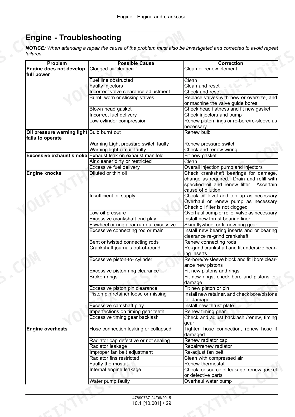
| Air cleaner maintenance | Clean or renew element | p. 52 |
| Lift piston working clearance | 0.036 – 0.091 mm (0.001 – 0.004 in) | p. 551 |
| Lift cylinder O-ring replacement | Replace the O–ring and back–up ring by new square seal | p. 598 |
| Lip seals replacement | Check lip seals (1) and (2) and replace if necessary | p. 442 |
Case IH JX55T–JX75T Common Problems This Manual Covers
Engine stalls immediately after cold start with no error codes showing on dash
Inspect the fuel shutoff solenoid: at key-on it should click and hold. Check fuel lines for blockage or air entry that collapses fuel delivery once the engine fires. Verify idle stabilizes at 650 RPM (page 26) once warm. If stalling repeats, trace the no-start flowchart on page 52 beginning with fuel delivery pressure.
Manual Section: Engine - 10 p. 52Hydraulic lift fails to raise implement or drops load intermittently during operation
Inspect the lift cylinder O-ring and back-up ring for seepage; replace both with a new square seal (page 598). Verify lift piston working clearance is within 0.036 – 0.091 mm (0.001 – 0.004 in) (page 551). If pressure is suspect, measure the pump relief valve spring against the 45.000 mm free-length spec on page 194.
Manual Section: Hydraulic Systems - 35Clutch slips or fails to fully disengage when pedal is fully depressed
Adjust clutch pedal free play to 45.000 – 50.000 mm before disassembly (page 222). If adjustment doesn't resolve slip, remove the clutch and measure transmission plate thickness: discard any plate below 8.800 mm (0.346 in). Verify control sleeve working clearance falls within 0.050 – 0.151 mm (0.002 – 0.006 in). Torque assembly mounting bolts to 26.0 N·m (19.2 lb ft).
Manual Section: Clutch - 18 p. 222Transmission gears grind, skip out of range, or are difficult to select
Check gearbox external controls for binding or misadjustment before pulling the transmission. If internal selectors slide with resistance, overhaul the control items as directed on page 266. Torque the transmission housing-to-engine bolts to 100.00 N·m (page 254) when reinstalling. Inspect shift forks and selector rails for wear or damage that prevents clean engagement.
Manual Section: Transmission - 21 p. 266Rear axle oil leak at wheel hub, differential overheating after extended work
Inspect lip seals (1) and (2) at the wheel hub and replace both if degraded (page 442). Drain the final drive and check for contaminated oil or scored bearing surfaces. Measure rear bevel drive backlash: spec is 0.150 – 0.200 mm (page 398). Reassemble and run for 30 minutes, then recheck hub temperature and check for fresh seepage.
Manual Section: Rear Axle System - 27 p. 442Frequently Asked Questions
What are the torque specs for the engine bolts on Case IH JX55T and JX75T?
The manual provides specific torque specifications for various engine bolts. For example, the cylinder head bolts (M12 X 1.25) require 40 N·m (354 lb in) plus an angular tightening of (125 – 135°) and then (135 – 145°). Main bearing caps (M14 X 1.25) require 80 N·m (708 lb in) plus 90° angular tightening. Crankshaft pulley hub (M30 X 1.5) requires 300 N·m (2655 lb in). p. 27
What are the replacement specifications for Fuel injector (IVECO engine)?
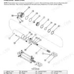
For JX75T Models, the injectors are MICO BOSCH, Nozzle holder KBEL 83S352 260 (apa), Nozzle DLLA 132S1320 with 5 spray orifices, a spray orifice diameter of 0.2300 mm (0.0091 in) / 0.2100 mm (0.0083 in), and a pressure setting of 260 – 272 Kg/cm² (3698 – 3869 psi). For JX55T Models, the injection pump is BOSCH VE4/12F1150LV16752, with 6 spray orifices, a spray orifice diameter of 0.1930 mm (0.0076 in), and a pressure setting of 260 – 268 Kg/cm² (3698 – 3812 psi). p. 138
What are the replacement specifications for Hydraulic pump?
The hydraulic pump is a gear type, driven by valve timing gear, with an engine/pump drive ratio of 1:0.931. Its maximum rated output is 32.800 L/min (8.665 US gpm) at 2328 RPM. For a new or reconditioned pump, the output at 1450 RPM and 166 bar (2407 psi) should be 19.100 L/min (5.046 US gpm). The test oil temperature should be 55 – 65 °C (131 – 149 °F). p. 512
How do you fix case IH JX75T black smoke from exhaust and power loss under heavy field load?
Check the air intake filter and clean or renew the element; a clogged filter alone can cause black smoke. Inspect MICO BOSCH fuel injectors for clogging: injector stand-out must be 0.050 – 0.700 mm (0.002 – 0.028 in) at reinstallation (page 158). Work through the smoke diagnosis flowchart on page 52 if symptoms persist. p. 52
What format is this manual in?
Instant PDF download. You get the full 767-page searchable Service Manual immediately after payment. Open it on your laptop, tablet, or phone right in the shop.
Can I print this manual?
Absolutely. No DRM or copy protection. Print the whole manual or just the pages you need. Any home or office printer works.
Can I find hydraulic circuit diagrams in this Case IH JX55–JX75 Series manual?
Included. Hydraulic system schematics cover all circuits, control valves, and component specifications for the Case IH JX55–JX75 Series.


Reviews
There are no reviews yet.