


Part of the JCB Repair Manuals.
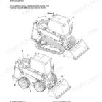
Factory-written for the 530-70, 532-120, 533-105, 535-60, and 535-95, this JCB A and R Series Side Engine Loadalls manual (OEM #9803/3630-14) runs 1,013 pages deep. Hydraulic coverage spans full schematics across construction, agricultural, Flowshare, and Wastemaster variants, matched by wiring diagrams that identify every relay and fuse on both Series I and Series II machines. Standard torque settings are covered in depth, with full error-code coverage and separate fault-finding for the powershift gearbox, ECU, brakes, hydraulic circuits, and steering. Torque the fuel inlet connector to 20 Nm (2.0 kgf m), and the flow regulator valve to the same figure, before the machine goes back to work. When the dealer quotes a week of downtime, search any spec by keyword and have your answer the same afternoon.
What's Inside This JCB A series, R series Manual
| System | Pages | Key Topics |
|---|---|---|
| General Information | 1-43 | Introduction, Identifying Your Machine, Standard Torque Settings, Service Tools, Service Consumables, Terms and Definitions |
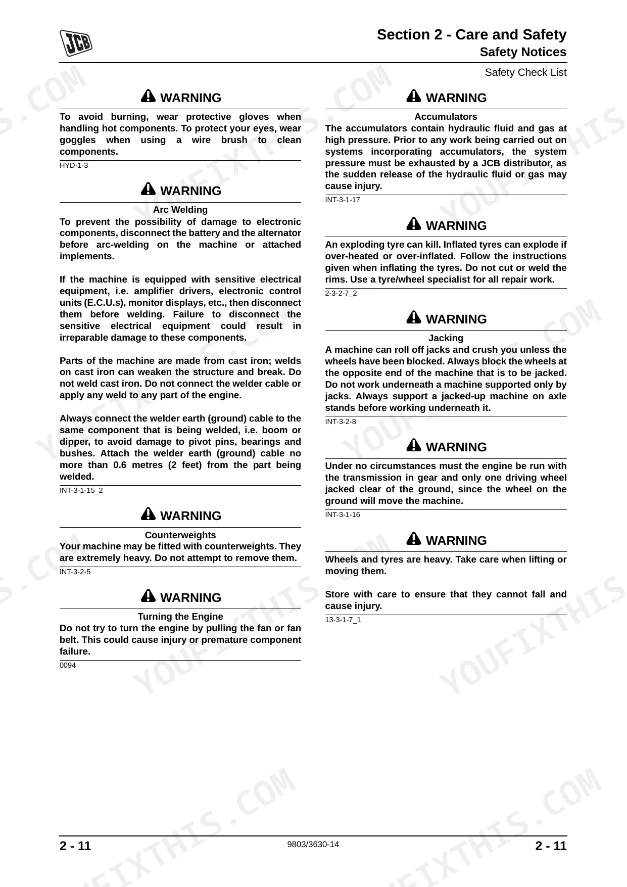
| Care and Safety | 44-61 | Safety Notices (Important Information, Operator Manual, Safety Warnings), Safety Check List (Safety - Yours and Others, Operating Safety, Maintenance Safety) |
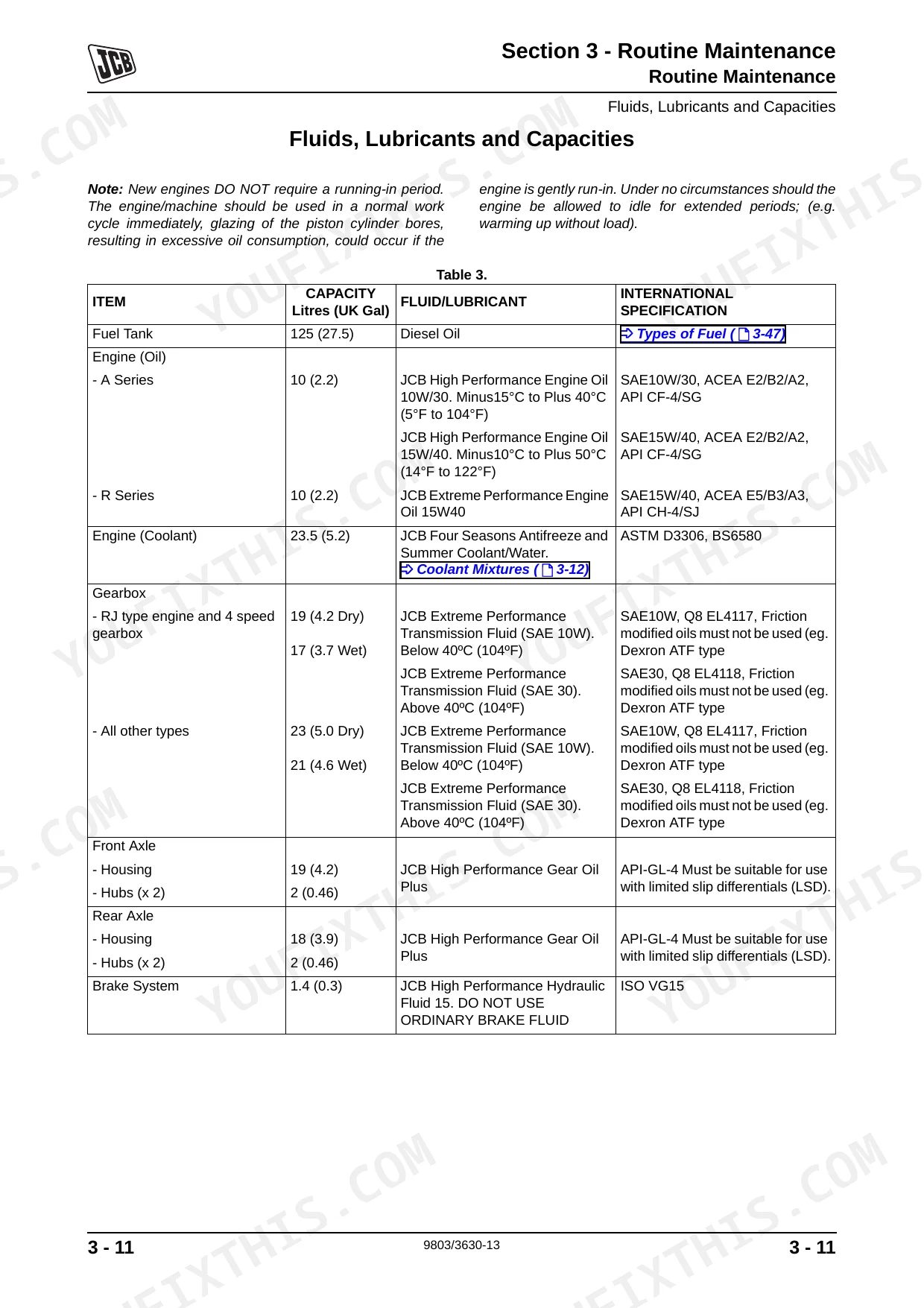
| Maintenance | 62-139 | Routine Maintenance (Health and Safety, Service Schedules, Fluids, Lubricants and Capacities, Cleaning the Machine, Checking for Damage, Seat Belt, ROPS/FOPS Structure, Boom Safety Strut, Greasing, Oiling, Engine Cover, Air Conditioning and Heater, Brakes, Electrical System, Engine Oil and Filter, Engine Air Filter, Engine Cooling System, Fuel System) |
| Attachments | 140-145 | Service Procedures, Quick Release Couplings, Connecting and Disconnecting, Quick Release Couplings - Do's and Don'ts, Connecting Quick Release Couplings |
| Body and Framework | 146-281 | Technical Data (Air Conditioning), Basic Operation (Boom - Telescopic Operation, Air Conditioning, Load Indicators) |
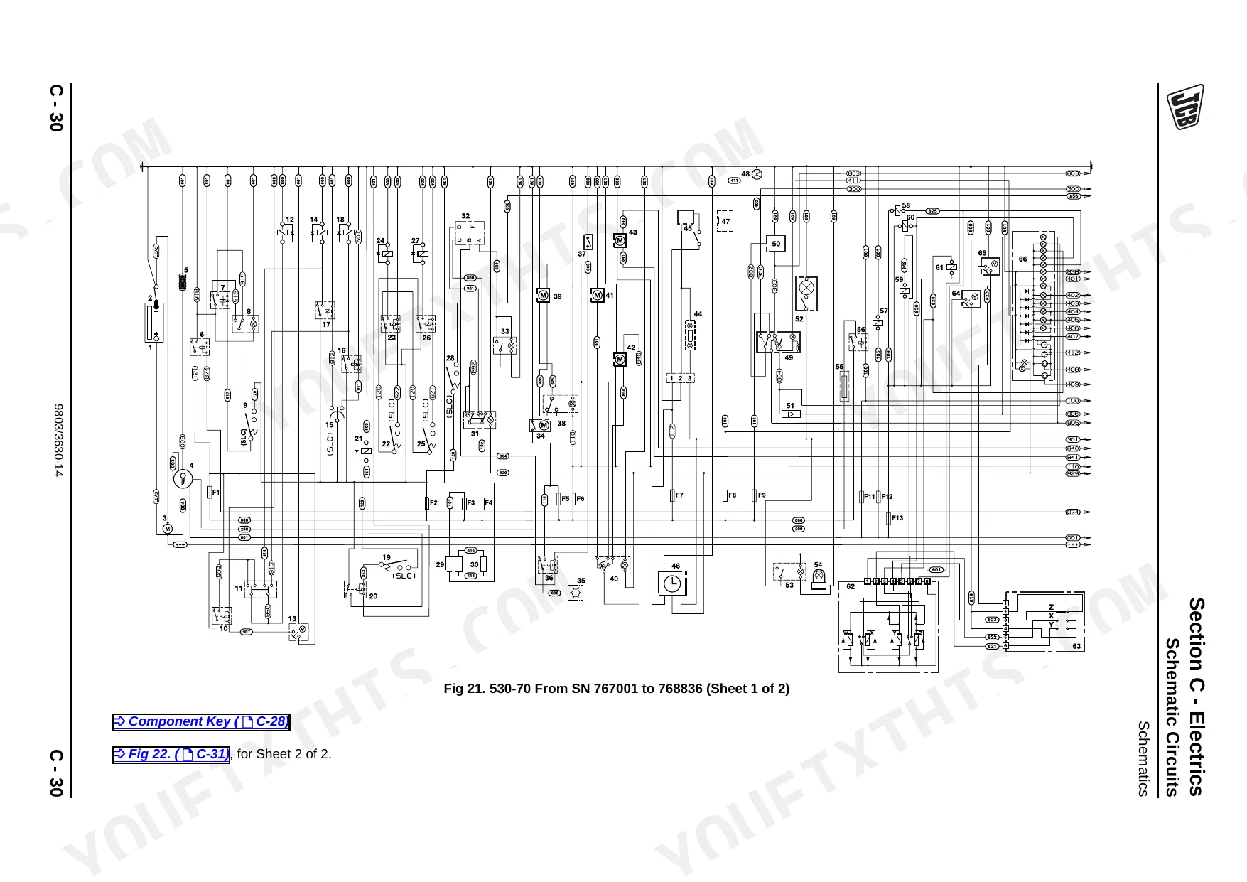
| Electrics | 282-421 | Technical Data (Relay Identification, Fuse Identification), Schematic Circuits (Applicable Machines, Schematics) |
| Controls | 422-427 | Accelerator Cable, Removal and Replacement, Testing and Adjustment |
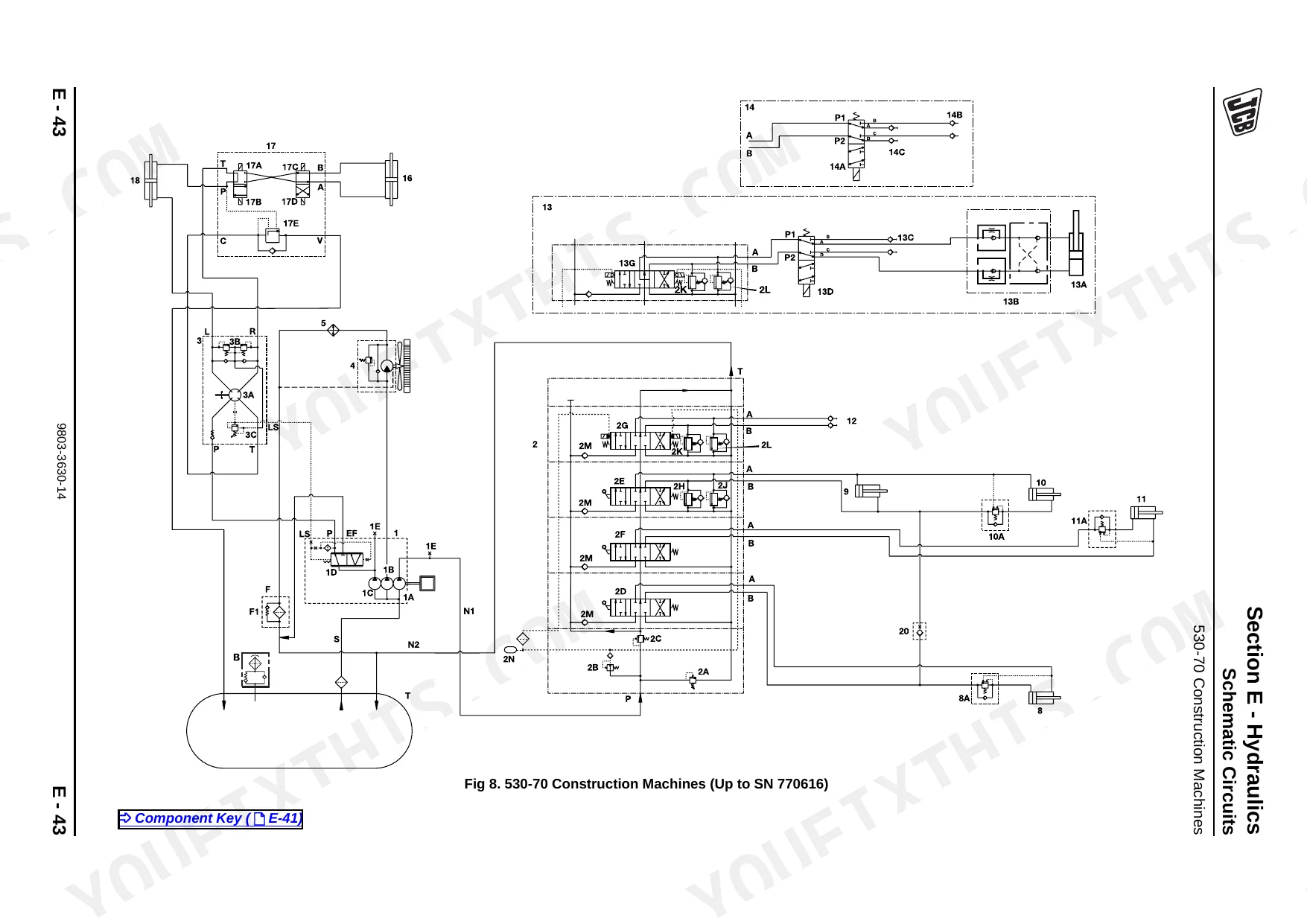
| Hydraulics | 428-703 | Technical Data (Agricultural and Wastemaster Machines, Construction Machines, Flowshare Machines, 532-120, 535-125, 535-140 Machines, Machines, Agricultural Machines, 537-135, 540-140, 550 Machines, 540-170, 550-170, 5508 Machines) |
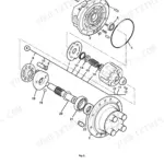
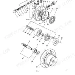
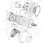
| Transmission | 704-847 | Technical Data (Tyre Pressures, Front Axles, Rear Axles, Powershift Gearboxes, Engine Stall Speed Combinations) |
| Brakes | 848-889 | Technical Data (Machines with SD55, SD70 Axles, Machines with SD80 Axles, Pedal Effort Versus Brake Pressure), Basic Operation, Fault Finding (Brake System) |
| Steering | 890-985 | Technical Data (All Machines), Basic System Operation (Hydraulic Operation, Electrical Operation), Electrical Connections (Series: I Machines, Ii Machines) |
| Engine | 986-1013 | Technical Data, Basic System Operation, Cooling Package, Fuel Lift Pump |
Quick Reference Specifications
| Specification | Value | Page |
|---|---|---|
| Location of torque specifications | Section 1 - General Information, Standard Torque Settings, pages 11-14 | p. 11 |
| Fuel filter element replacement instruction | Change filter element | p. 71 |
| Fuel inlet connector torque | 20 Nm (15 lbf ft, 2.0 kgf m) | p. 1012 |
| Flow regulator valve torque | 20 Nm (2 kgf m, 14.8 lbf ft) | p. 172 |
| Fuel inlet connection union nut torque | 20 Nm (15 lbf ft, 2.0 kgf m) | p. 1012 |
| Air filter inner element replacement interval | Every third time the outer element is changed | p. 107 |
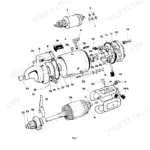
| Starter motor brush minimum length | 8 mm (0.3 in.) | p. 420 |
| Starter motor commutator minimum diameter | 38 mm (1.5 in.) | p. 420 |
| Battery electrolyte level above plates | 6 mm (1/4 in.) | p. 100 |
| Battery voltage | 12 volts | p. 286 |
| Alternator brush minimum length | 5 mm (0.2 in.) | p. 416 |
JCB A series, R series Common Problems This Manual Covers
JCB Loadall engine cranks but won't start or stalls shortly after, fuel pressure suspect
Start at the fuel filter and replace it if it's overdue, then confirm the lift pump is delivering fuel by cracking the bleed screw downstream. Inspect every suction-side hose for cracks or loose clips that let air in; a pinhole is enough to kill prime. On reassembly, torque the fuel inlet connector to 20 Nm (15 lbf ft). Read the fault codes on page 71 for D002 (water in fuel) or D003 before condemning the pump.
Manual Section: Fuel System p. 1012Engine overheats and D004 coolant temperature fault code appears on the display
Confirm the coolant level and top up if it's low, then look over the hoses and radiator face for leaks or debris blockage. Pull and test the thermostat; a stuck-closed unit is a common culprit. If coolant keeps dropping with no visible external leak, measure compression pressure: normal range is 20-35 bar (290-507 lbf/in2), and a low cylinder points to the head gasket. Cross-check codes D010 and D218 on page 71 to tell sensor faults from a genuine overheat.
Manual Section: Engine Cooling System p. 991Alternator not charging, D205 fault code logged, battery warning light on
Measure battery voltage at the terminals; it should read 12 volts at rest. Run the alternator charging test on pages C-120 to C-121, where maximum rated output is 65 amp. Inspect the brush assembly and replace brushes worn below 5 mm (0.2 in). Check drive belt tension and all earth straps for corrosion before condemning the alternator itself.
Manual Section: Alternator Charging Test p. 416Boom lifts slowly under load or hydraulic functions feel weak and unresponsive
Inspect the hydraulic filter, rated at 10 microns (0.0004 in); a blocked element starves the whole circuit. Check the hydraulic oil level and look for intake-side leaks pulling air in. On machines with flowshare valves, work through the fault finding on pages E-102 to E-104 to isolate lack-of-power causes. If the engine stalls under hydraulic demand, check how the engine relief and load-sense circuits interact before assuming pump failure.
Manual Section: Hydraulic Flowshare (LSV) Valve Block Fault Finding p. 437Machine won't move or loses drive intermittently, no gearbox noise
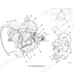
Pull the fault codes first; pages F-110 to F-113 cover no-drive and intermittent-drive diagnosis for the transmission ECU. Check the powershift gearbox fluid level and condition, since contaminated fluid causes pressure loss. Inspect the ECU harness connectors for moisture or corrosion, especially around the transmission electrical pinout shown. Verify fuse integrity before suspecting internal gearbox failure.
Manual Section: Electronic Control Unit (ECU) Fault Finding (Transmission)Air filter restriction warning D001 active, noticeable drop in power under load
Remove and inspect the outer air filter element, and replace it if it's contaminated. Change the inner element every third time the outer is replaced. Check the intake ducting and hose clamps between the filter housing and turbo inlet for cracks that bypass filtration entirely. After service, clear the D001 code on page 71 and recheck under load; a power loss that lingers after a clean filter points to a boost leak or an intake manifold pressure sensor fault (code E009).
Manual Section: Engine Air Filter p. 107Frequently Asked Questions
What does JCB error code mean?
Load Indicator fault codes are listed with their causes and remedies. Fault Code 1, for example, flags a "Transducer signal fault," usually because the transducer isn't connected; the fix is to check that connection. The rest of the codes follow the same cause-and-remedy format. p. 216
What are the torque specs for JCB A Series/R Series components?
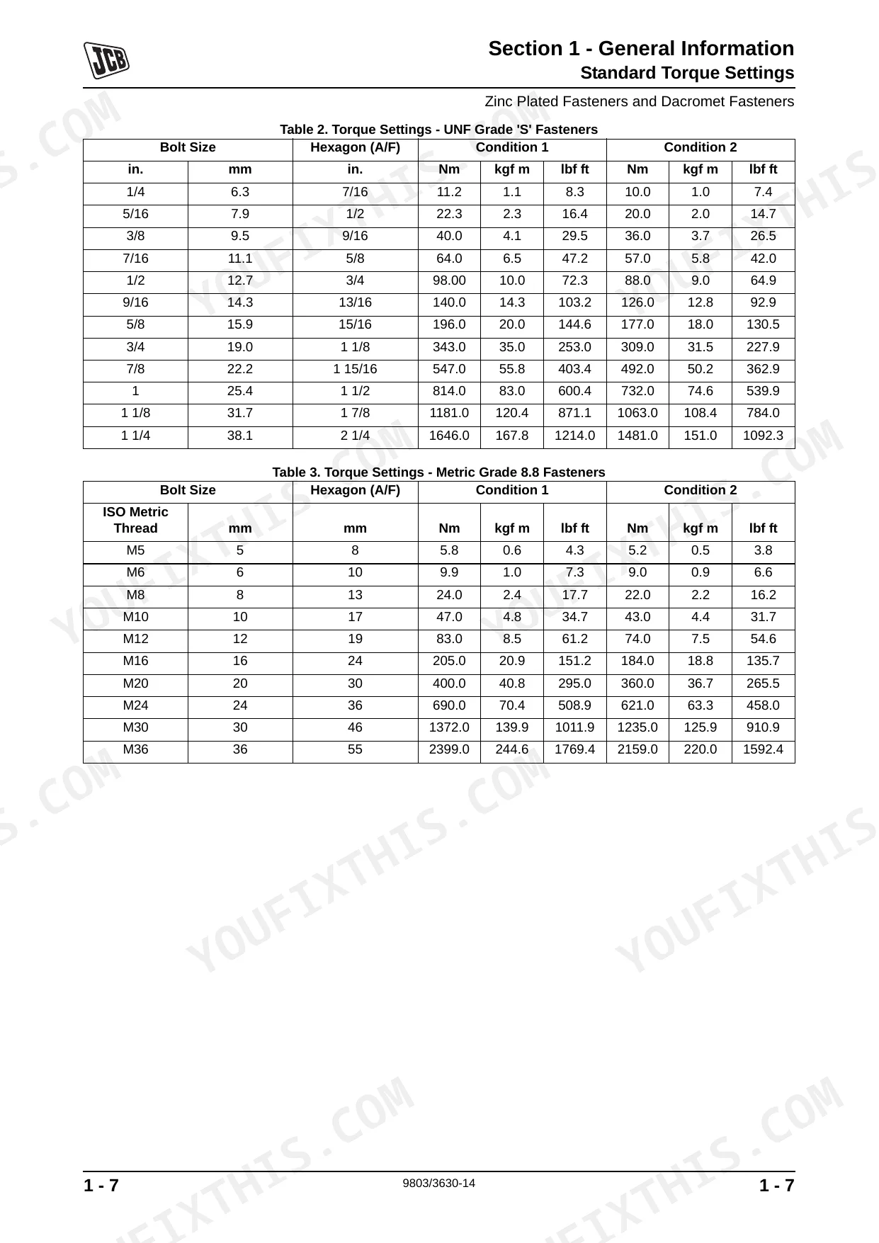
Standard torque settings are tabulated by fastener type. A 1/4 inch UNF Grade 'S' fastener takes 11.2 Nm (8.3 lbf ft) at Condition 1 (un-lubricated, zinc, or yellow plated threads), while an M5 Metric Grade 8.8 bolt takes 5.8 Nm (4.3 lbf ft) at the same condition. Individual components carry their own figures too, such as 244Nm (180 lbf ft) for the ROPS/FOPS Bolts 3-A. p. 12
What format is this manual in?
A 1013-page Service Manual in searchable PDF, ready the moment checkout completes. View it on computer, tablet, or phone, with no shipping wait.
Is this JCB A series, R series Service Manual printable?
The PDF is DRM-free, so print whatever sections you need for the shop floor. Standard letter or A4 paper works fine.
Are there wiring harness diagrams in this JCB A series, R series manual?
Yes. You'll find full electrical schematics with wire routing diagrams, connector identification, and circuit descriptions.
Reviews
There are no reviews yet.