

Part of the JCB Repair Manuals.
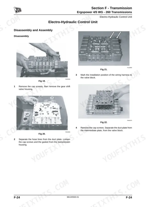
When it is time to tear down the powershift transmission or pull the centre pivot on your Wheeled Loading Shovel, this 746-page JCB 467 service manual PDF (OEM #9813/0500-01) gives you the exact factory blueprint. Inside, you get complete brake circuit diagrams, hydraulic schematics with fault-finding charts, and step-by-step teardown procedures for the loader arms and axles. Open to the electrical section to find wiring harness repair instructions and torque tables for every fastener grade on your machine. Swap out the transmission oil and filter at the 500-hour mark, and tighten those 1/4-inch UNF Grade S fasteners to exactly 11.2 Nm. A dead loader leaves your crew standing around. Pull up this file on your shop tablet and get your equipment moving again.
What's Inside This Manual
| System | Pages | Key Topics |
|---|---|---|
| General Information | About This Publication, Schematic Codes, Moving a Disabled Machine, Torque Settings, Service Tools, Sealing and Retaining Compounds | |
| Care and Safety | Important Information, Safety Check List, Safety Labels, Operating Safety, Maintenance Safety, Fluid Under Pressure | |
| Maintenance | Service Schedules, Fluids, Lubricants and Capacities, Prepare the Machine for Maintenance, Greasing, Electrical System, Engine Oil and Filter | |
| Section a - Attachments | Connecting/Disconnecting Hydraulic Hoses, Quick Release Couplings, Quickhitch Removal, Quickhitch Ram Installation | |
| Section B - Body and Framework | Cab Removal and Replacement, Loader Arms Reset Mechanism, Centre Pivot Removal, Cooling Pack Dismantling, Air Conditioning Component Location | |
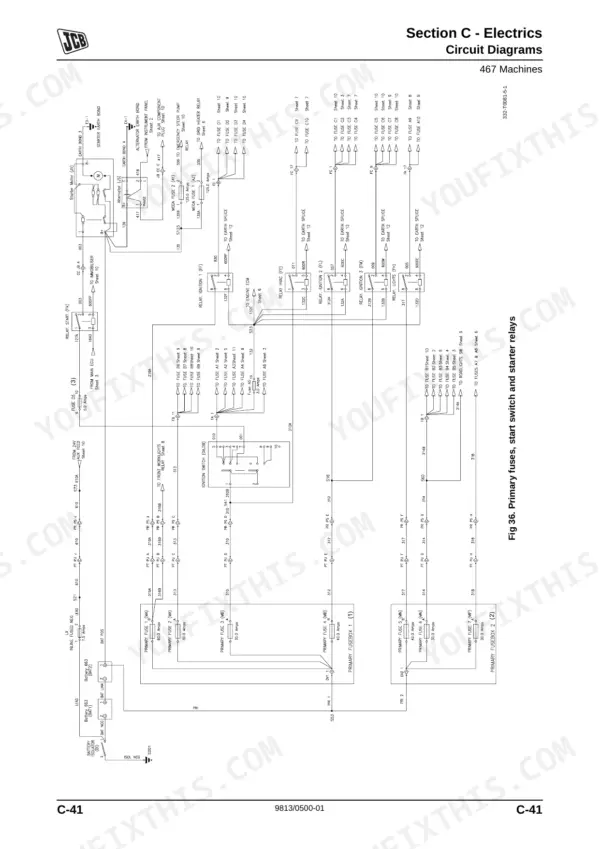
| Section C - Electrics | General Electrical Data, Using a Multimeter, Battery Maintenance, Wiring Harness Repair, Circuit Diagrams, Servicemaster Diagnostics | |
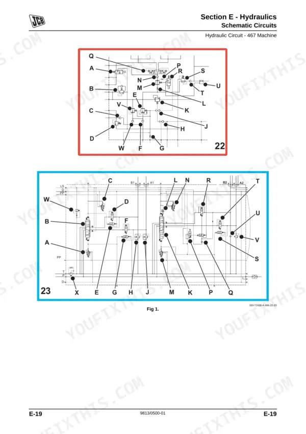
| Section E - Hydraulics | Technical Data, Hydraulic Schematic Symbols, Pump Operation, Pressure Testing, Hydraulic Fault Finding | |
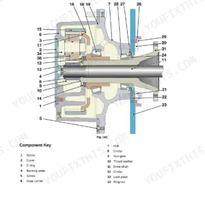
| Section F - Transmission | Technical Data, Powershift Transmission Description, Transmission Disassembly, Axle Disassembly, Pinion Depth Adjustment, Driveshafts Removal | |
| Section G - Brakes | Technical Data, Brake Circuit Diagrams, Bleeding the System, Park Brake Adjustment, Service Brake Testing, Accumulator Charging | |
| Section H - Steering | Technical Data, Steering Valve Operation, Emergency Steering Operation, Hydraulic Steering Unit Removal, Emergency Steering Pump System, System Pressure Adjustment | |
| Section K - Engine | Technical Data, Engine Specifications, Running-In Period |
Quick Reference Specifications
| Specification | Value | Page |
|---|---|---|
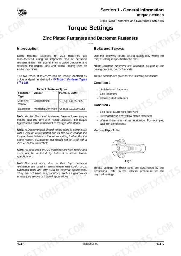
| Torque Settings - UNF Grade 'S' Fasteners (1/4 in bolt, Condition 1) | 11.2 Nm (1.1 kgf m, 8.3 lbf ft) | p. 20 |
| Torque Settings - Metric Grade 8.8 Fasteners (M5 bolt, Condition 1) | 5.8 Nm (0.6 kgf m, 4.3 lbf ft) | p. 20 |
| Hydraulic Fault Finding - Lack of power in all hydraulic functions (Possible Causes) | Insufficient hydraulic fluid; Hydraulic leaks in system; Engine performance; Pump control setting incorrect; Low pump flow; Priority valve sticking | p. 431 |
| Hydraulic Fault Finding - Lack of power in all hydraulic functions (Actions) | Check for leaks and top up as required; Check hoses, replace as required; Check engine performance; Check and adjust as required; Check pump flow; Check priority valve | p. 431 |
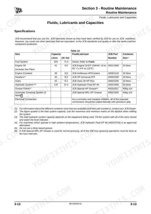
| Transmission Oil and Filter Change Interval | 500 hours | p. 69 |
| Transmission Breather Filter Check Interval | 500 hours | p. 69 |
| Hydraulic Filter Change Interval | 500 hours | p. 69 |
| Hydraulic Tank Breather Filter Check Interval | 500 hours | p. 69 |
| Engine Oil Capacity (Includes the Filter) | 41 Litres (9.0 UK Gal) | p. 75 |
| Engine Coolant Capacity | 39 Litres (8.5 UK Gal) | p. 75 |
| Fuel Filter/Water Separator Drain Interval | 50 hours | p. 70 |
| Fuel Filter/Water Separator Change Interval | 500 hours | p. 69 |