


Need the factory part numbers for your Kubota L3410DT, L3410GST, or L3410HST tractor? This 567-page catalog splits out all three transmission variants (DT, GST, and HST documented separately), so the parts list in front of you always matches the machine in your shop. Roughly 200 pages pair itemized parts lists with exploded views: crankcase, injection pump, HST unit, front differential, hydraulic cylinder, 3-point linkage, ROPS, and cab hardware, right down to every tire and wheel option. Each view ties a part number, description, and quantity to the component you can see, and cross-references flag serial number applicability. Head to the electrical section and the fuse ratings sit right there: 10A, 15A, and 40A by circuit. Bookmarks drop you onto any assembly in seconds, which beats thumbing through a paper book at the parts counter.
What's Inside This Kubota L3410DT, L3410GST, L3410HST Parts Manual
| System | Pages | Key Topics |
|---|---|---|
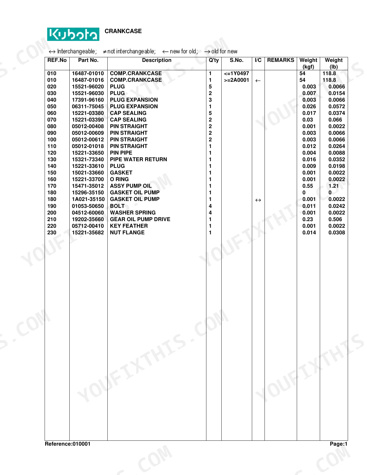
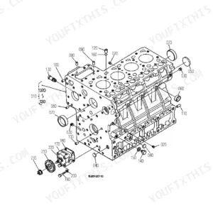
| Crankcase | 9-10 | Comp.Crankcase (Plug, Plug Expansion) |
| Oil Pan | 11-13 | Oil Pan Diagram, Oil Pan Diagram (Part 110), Parts List, Gasket Oil Pan, Bolt |
| Cylinder Head | 14-15 | Hook Engine (Cap Protector, Blank) |
| Gear Case | 16-17 | Assy Case Gear (Plug, O Ring) |
| Head Cover | 18-19 | Plate B/Ther Element (Element Breather, Oil Shield Breather) |
| Main Bearing Case | 20-22 | Assy Brg.Case Wheel (Bolt Bearing Case, Gasket Bearing Case) |
| Camshaft and Idle Gear Shaft | 23-25 | Tappet (Push Rod, Assy Camshaft) |
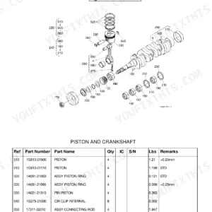
| Piston and Crankshaft | 26-27 | Piston (Assy Piston Ring, Pin Piston) |
| Flywheel [W/O Ind-Pto] | 28-29 | Comp.Flywheel (Gear Ring, Bolt Flywheel) |
| Flywheel [With Ind-Pto] | 30-31 | Comp.Flywheel (Gear Ring, Bolt Flywheel) |
| Fuel Camshaft and Governor Shaft | 32-33 | Assy Camshaft Fuel (Bearing Ball) |
| Engine Stop Lever | 34-35 | Apparatus Idling (Assy Bolt Adjustment, Nut) |
| Injection Pump | 36-37 | Assy Pump Injection (Shim Injection Pump, Blank) |
| Injection Pump [Component Parts] | 38-39 | Assy Pump Injection (Plunger Pump, Valve Delivery) |
| Governor | 40-42 | Comp.Lever Governor (Assy Lever Fork, Comp.Lever Fork) |
| Speed Control Plate | 43-45 | Assy Bolt Adjustment (Bolt Adjusting, Nut) |
| Nozzle Holder and Glow Plug | 46-48 | Assy Pipe Over Flow (Assy Tube Fuel, Tube Fuel) |
| Nozzle Holder [Component Parts] | 49-51 | Kit Holder Nozzle (Nut, Washer Adjusting), Seal Heat |
| Water Flange and Thermostat | 52-53 | Comp.Flange Water (Pipe Water Return, Gasket Water Flange) |
| Water Pump | 54-56 | Assy Pump Water (Body Water Pump, Bearing) |
| Valve and Rocker Arm | 57-59 | Valve Inlet (Valve Exhaust, Spring Valve) |
| Inlet Manifold | 60-62 | Manifold Inlet (Gasket In-Manifold, Bolt) |
| Upper Gasket Kit | 63-64 | Kit Gasket Upper (O Ring, Gasket Cyl.Head) |
| Lower Gasket Kit | 65-67 | Kit Gasket Lower (Gasket Oil Pan) |
| Exhaust Manifold/Muffler | 68-70 | Manifold Exhaust (Gasket Muffler, Stud) |
| Air Cleaner | 71-73 | Assy Cleaner Air (Comp.Body A/C, Assy Element Inner) |
| Stop Solenoide/Engine Stop Wire | 74-75 | Solenoid Stop (Bolt, Lever Stop) |
| Accelerator Lever [Except HST Type] | 76-77 | Grip (Shaft Accel.Control, Support Accel.Lever) |
| Accelerator Lever [Hst Type] | 78-79 | Grip (Shaft Accel.Control, Support Accel.Lever) |
| Accelerator Linkage [Except HST Type] | 80-81 | Spring (Rod Accel., Washer Plain) |
| Accelerator Rod [Except HST Type] | 82-83 | Rod Pedal (Washer Plain, Pin Split) |
| Accelerator Rod [Hst Type] | 84-85 | Cushion (Assy Rod Accel., Nut) |
| Fuel Tank | 86-88 | Kit Fuel Tank (Assy: Cap Fuel Tank) |
| Fuel Pipe and Fuel Filter | 89-91 | Assy Filter Fuel (Assy Tube Fuel, Clip Pipe) |
| Fuel Filter [Component Parts] | 92-93 | Assy Filter Fuel (Assy Body, Handle Filter) |
| Fan | 94-95 | Fan Diagram, Parts List, Bolt Flange, Pulley Fan |
| Water Pipe | 96-97 | Pipe Water (Band, Hose) |
| Radiator | 98-99 | Assy Radiator (Shroud Fan, Assy Cap) |
| Reserve Tank | 100-101 | Tank Reserve (Cap, Gasket) |
| Alternator | 102-104 | Stay Alternator (Pulley Fan Drive, Key Feather) |
| Alternator [Component Parts] | 105-106 | Assy Alternator (Pulley Alternator, Nut) |
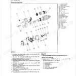
| Starter | 107-108 | Assy Starter (Stud, Nut) |
| Starter [Component Parts] | 109-110 | Assy Starter (Yoke, Armature) |
| Battery | 111-112 | Battery Diagram, Parts List, Label Battery, Cap Battery |
| Switch 1 [Except HST Type] | 113-115 | Timer Key Stop (Controller, Relay Glow) |
| Switch 1 [Hst Type] | 116-118 | Timer Key Stop (Controller, Relay Glow) |
| Switch 2 [Except HST Type] | 119-120 | Switch Oil (Sensor Thermo, Gasket) |
| Switch 2 [Hst Type] | 121-123 | Switch Oil (Sensor Thermo, Gasket) |
| Panel Board | 124-125 | Assy Panel (Cable Flexible, O Ring) |
| Panel Board [Component Parts] | 126-127 | Assy Panel (Hood Panel, Assy Tachometer) |
| Light [Old Type] | 128-130 | Assy Light Head (Bulb, Assy Wire Harness) |
| Light [New Type] | 131-132 | Assy Light Head (Bulb, Assy Wire Harness) |
| Electrical Wiring [Except HST Type] | 133-135 | Wire Harness (Assy Box Fuse, Cover Fuse Box) |
| Electrical Wiring [Hst Type] [Old Type] | 136-138 | Wire Harness Hst (Assy Box Fuse, Cover Fuse Box) |
| Electrical Wiring [Hst Type] [New Type] | 139-141 | Wire Harness Hst (Assy Box Fuse, Cover Fuse Box) |
| Clutch | 142-143 | Assy Plate Pressure (Pin Straight, Bolt) |
| Clutch Lever | 144-145 | Lever Clutch (Case Propeller Shaft, Bolt) |
| Clutch Pedal [Except HST Type] | 146-147 | Comp.Pedal Clutch (Bush, Seal Oil) |
| Clutch Pedal [Hst Type] | 148-150 | Comp.Pedal Clutch (Bush, Seal Oil) |
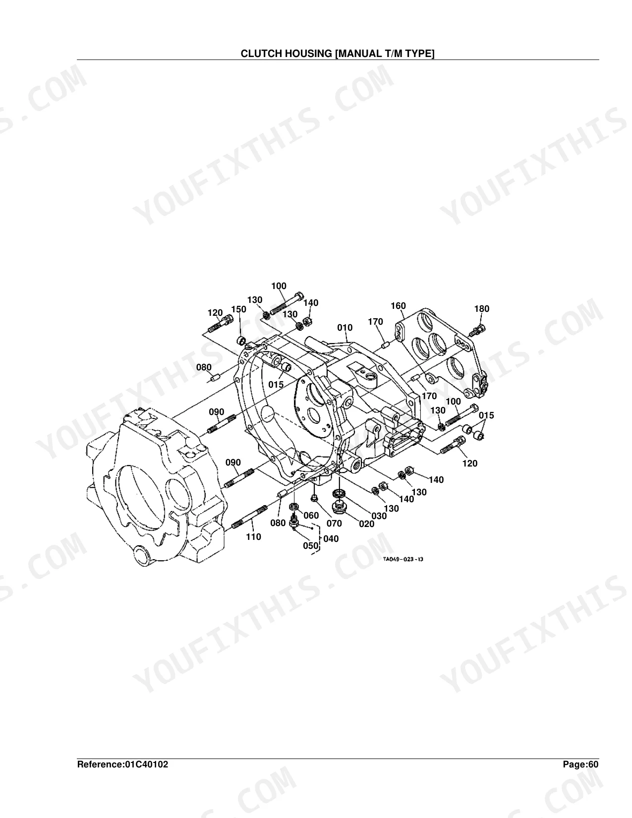
| Clutch Housing [Manual T/M Type] | 151-152 | Housing Clutch (Bush, Plug Drain) |
| Clutch Housing [Gst Type] | 153-154 | Housing Clutch (Bush, Plug Drain) |
| Clutch Housing [Hst Type] | 155-157 | Assy Housing Clutch (Bush, Plug Drain) |
| Gst Valve [Gst Type] | 158-159 | Assy Valve Gst (Pipe Hydraulic, Bolt) |
| Gst Valve [Gst Type] [Component Parts] | 160-166 | Assy Valve Gst (O Ring, Plug) |
| Mid Case [Manual T/M Type] [With Ind-Pto] | 167-168 | Case Mid (Holder, Piston) |
| Mid Case [Gst Type] [W/O Ind-Pto ] | 169-170 | Case Mid (Holder Bearing, Pin Straight) |
| Mid Case [Hst Type] [Old Type] | 171-172 | Case Mid Hst (Holder Bearing, Pin Straight) |
| Mid Case [Hst Type] [New Type] | 173-174 | Case Mid Hst (Holder Bearing, Pin Straight) |
| HST [Component Parts] | 175-178 | Assy Hst (Case Hst, Shaft Pump) |
| Transmission Case [Manual T/M Type] | 179-180 | Case Transmission (Gauge Oil, Pin Straight) |
| Transmission Case [Gst Type] | 181-182 | Case Transmission (Gauge Oil, Pin Straight) |
| Transmission Case [Hst Type] | 183-184 | Case Transmission (Gauge Oil, Pin Straight) |
| Main Shaft [Except HST Type] [W/O Ind-Pto] | 185-186 | Gear-Shaft Pto (Bearing Ball, Gasket Bearing Ball) |
| Main Shaft [Except HST Type] [With Ind-Pto] | 187-188 | Gear-Shaft (Bearing Ball, Seal Oil) |
| Main Shaft [Hst Type] | 189-190 | Gear-Shaft Pto (Bearing Ball, Seal Oil) |
| Input Shaft [Hst Type] | 191-192 | Gear-Shaft (Cir Clip External) |
| Countershaft [Manual T/M Type] | 193-194 | (Bearing Ball, Cir Clip Internal) |
| Countershaft [Gst Type] | 195-196 | (Bearing Ball, Cir Clip Internal) |
| Output Shaft [Hst Type] | 197-198 | Gear-Shaft Hst (Coupling, Pin Spring) |
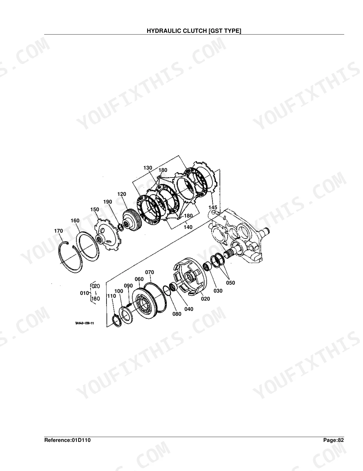
| Hydraulic Clutch [Gst Type] | 199-200 | Assy Clutch (Case Clutch, Bearing Needle) |
| Shuttle Shaft [Manual T/M Type] | 201-202 | Shaft Shuttle (Cir Clip External, Washer) |
| Shuttle Shaft [Gst Type] | 203-204 | Shaft Shuttle (Cir Clip External, Cir-Clip) |
| Range Gear Shaft [Manual T/M Type] | 205-206 | Collar Thrust, Bearing Needle |
| Range Gear Shaft [Gst Type] | 207-208 | Collar Thrust, Bearing Needle |
| Spiral Bevel Pinion [Except HST Type] [W/O Creep] | 209-210 | Gear 4Wd (Blank, Cir Clip External) |
| Spiral Bevel Pinion [Except HST Type] [With Creep] | 211-212 | Gear 4Wd (Blank, Cir Clip External) |
| Spiral Bevel Pinion [Hst Type] | 213-214 | Gear 4Wd (Cir Clip External, Gear-Shaft) |
| Rear Differential | 215-216 | Assy Differential (Case Differential, Cover Diff.Case) |
| PTO Countershaft [Except HST Type] [With Ind-Pto] | 217-218 | Gear-Shaft I-Pto (Bearing: Roller, Ball) |
| PTO Countershaft [Except HST Type] [W/O Ind-Pto] | 219-220 | Countershaft Pto (Cir Clip External, Bearing Ball) |
| PTO Clutch [Except HST Type] [With Ind-Pto] | 221-223 | Gear-Shaft I-Pto (Assy Clutch I-Pto, Case Pto Clutch) |
| PTO Clutch [Except HST Type] [W/O Ind-Pto] | 224-225 | Spring One-Way (Cam Clutch, Washer) |
| PTO Clutch [Hst Type] [W/O Ind-Pto] | 226-227 | Countershaft Pto (Bearing Ball, Gear Pto) |
| PTO Shaft [Except HST Type] | 228-229 | Gear (Collar Thrust, Bearing Needle) |
| PTO Shaft [Hst Type] | 230-231 | Gear (Collar Thrust, Bearing Needle) |
| Mid PTO [Except HST Type] | 232-233 | Gear M-Pto, Bearing Ball, Collar, Gear-Shaft M-Pto, Seal Oil Mid PTO, Cir Clip Internal |
| Mid PTO [Hst Type] | 234-235 | Gear M-Pto, Bearing Ball, Collar, Gear-Shaft M-Pto, Seal Oil Mid PTO, Cir Clip Internal |
| Main Gear Shift Fork [Manual T/M Type] | 236-237 | Fork Main Shift (Rod Fork, Pin Spring) |
| Main Gear Shift Fork [Gst Type] | 238-239 | Fork Main Shift (Rod Fork, Pin Spring) |
| Shuttle Shift Fork [Manual T/M Type] | 240-241 | Fork Shuttle Shift (Bolt Reamer, Washer) |
| Shuttle Shift Fork [Gst Type] | 242-243 | Fork Shuttle Shift (Bolt Reamer, Washer) |
| Range Gear Shift Fork/Creep Gear Shift Fork | 244-247 | Fork Creep Shift (Rod Fork, Pin Spring) |
| Range Gear Shift Fork [Hst Type] | 248-249 | Fork Range Shift (Rod Shiff, Spring) |
| Differential Lock Shift Fork [Except HST Type] | 250-252 | Fork Diff.Lock Shift (Pin Joint, Washer Plain) |
| Differential Lock Shift Fork [Hst Type] | 253-255 | Fork Diff.Lock Shift (Pin Joint, Washer Plain) |
| Rear Axle | 256-257 | Shaft Diff.Gear Rh (Shaft Diff.Gear Lh, Bearing Ball) |
| Brake | 258-260 | Case Brake Lh (Case Brake Rh, Pin Straight) |
| Brake Rod 1 [Except HST Type] | 261-262 | Assy Lever Brake Lh (Bush, Assy Lever Brake Rh) |
| Brake Rod 1 [Hst Type] | 263-265 | Assy Lever Brake Lh (Bush, Assy Lever Brake Rh) |
| Brake Rod 2 [Manual T/M Type] | 266-267 | Rod Brake Lh (Rod Brake Rh, Pin Joint) |
| Brake Rod 2 [Gst Type] | 268-269 | Rod Brake Lh (Rod Brake Rh) |
| Brake Rod 2 [Hst Type] | 270-271 | Case Brake Lh (Case Brake Rh, Pin Straight) |
| Main Gear Shift Lever [Manual T/M Type] | 272-273 | Collar Thrust, Bearing Needle |
| Main Gear Shift Lever [Gst Type] | 274-275 | Collar Thrust, Bearing Needle |
| Shuttle Shift Lever [Except HST Type] | 276-278 | Grommet, Lever Shuttle, Grip Lever, Bolt Reamer, Spring, Collar Shuttle |
| Cruise Control Lever [Hst Type] | 279-280 | Rod, Ball Link, Shaft, Lever HST Link, Pin Spring, Bracket |
| Cruise Control Cable [Hst Type] | 281-282 | Wire Control, Pin Snap, Lever, Wire PTO, Grommet, Pin Joint |
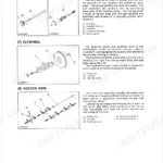
| Neutral Holder Link [Hst Type] | 283-285 | Bracket HST, Assy Arm, Arm Neutral Holder, Shaft Holder, Bearing Ball, Damper HST |
| Speed Control Pedal [Hst Type] | 286-287 | Rod, End Rod, Assy Pedal, Cover HST Pedal, Pin HST Pedal, Bolt Flange |
| Range Gear Shift Lever [Manual T/M Type] | 288-289 | Collar Thrust, Bearing Needle |
| Range Gear Shift Lever [Hst Type] | 290-292 | Collar Thrust, Bearing Needle |
| Range Gear Shift Lever/Creep Gear Shift Lever | 293-294 | Collar Thrust, Bearing Needle |
| Range Gear Shift Rod [Hst Type] [Old Type] | 295-296 | Collar Thrust, Bearing Needle |
| Range Gear Shift Rod [Hst Type] [New Type] | 297-298 | Collar Thrust, Bearing Needle |
| Creep Gear Shift Lever [Gst Type] | 299-300 | Collar Thrust, Bearing Needle |
| PTO Clutch Control Lever [Manual T/M Type] | 301-302 | Assy Plate Pressure (Pin Straight, Bolt) |
| PTO Gear Shift Lever [Gst Type] [W/O Ind-Pto] | 303-304 | Collar Thrust, Bearing Needle |
| PTO Gear Shift Lever [Hst Type] [W/O Ind-Pto] | 305-306 | Collar Thrust, Bearing Needle |
| PTO Clutch Valve [Component Prts] [With Ind-Pto] | 307-308 | Assy Plate Pressure (Pin Straight, Bolt) |
| Mid PTO Shift Lever [Except HST Type] | 309-310 | Lever M-Pto (Pin Spring, Rod) |
| Mid PTO Shift Lever [Hst Type] | 311-312 | Lever M-Pto (Pin Spring, Rod) |
| Front Wheel Drive Lever | 313-314 | Lever Shift, O Ring, Stopper, Bolt Flange, Lever 4Wd Change, Grip Lever |
| Brake Pedal [Except HST Type] | 315-317 | Case Brake Lh (Case Brake Rh, Pin Straight) |
| Brake Pedal [Hst Type] | 318-320 | Case Brake Lh (Case Brake Rh, Pin Straight) |
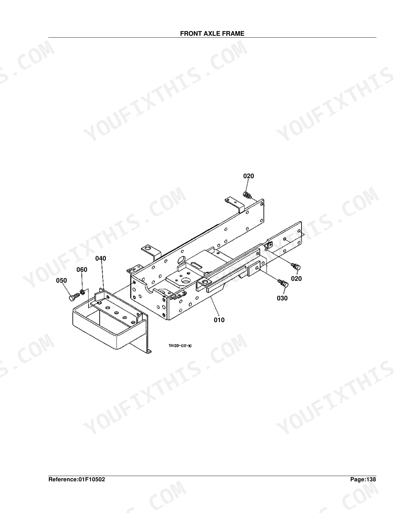
| Front Axle Frame | 321-322 | Comp.Frame F-Axle, Bolt, Bumper, Washer Spring |
| Propeller Shaft | 323-325 | Shaft Propeller, Coupling, Pin Spring, Bearing Ball, Seal Oil, Cover Shaft Front |
| Front Wheel Drive Shaft | 326-327 | Shaft Mid PTO, Bearing Ball, Spring, Ball, Gear 4Wd Shift |
| Front Differential Case | 328-330 | Case Front Axle, Plug, Washer with Rubber, Pipe Breather, O Ring, Bolt |
| Front Differential | 331-332 | Assy Gear Bevel, Bearing Taper-Roller, Collar, Seal Oil, Case Diff., Shaft Pinion |
| Front Axle Case | 333-334 | Shaft Bevel Gear, Case Front Gear Rh, Plug, Seal Oil, Bearing Ball, Shim |
| Differential Gear Shaft | 335-336 | Collar Thrust, Bearing Needle |
| Front Axle | 337-338 | Axle Front, Bearing Ball, Gear Bevel, Collar, Seal Oil, Cover Front Axle |
| Steering Handle [Except HST Type] | 339-340 | Cover Steering Post, Assy Post Steering, Shaft Steering, Coupling Steering, Lever Tilt, Assy Wheel Steering |
| Steering Handle [Hst Type] | 341-343 | Assy Post Steering, Shaft Steering, Coupling Steering, Assy Wheel Steering, Holder Tilt, Grip |
| Steering Contoller | 344-346 | Controller Steering, Seal Oil, Plug, O Ring, Comp.Valve Relief, Adapter Cylinder |
| Steering Linkage | 347-348 | Assy Rod Tie Lh, Cover Dust, Clip, Nut, Pin Split, Rod Adjusting |
| Steering Cylinder | 349-350 | Assy Cylinder Strg., Support Shaft, Assy Arm Pitman, Shaft Pitman Arm, Shaft Rod End, Plate Rod End |
| Steering Cylinder [Component Parts] | 351-352 | Assy Rod, Gasket Piston, O Ring, Assy End Rod, Tube Cylinder, Assy Cover Cylinder |
| Hydraulic Pump [Except HST Type] | 353-354 | Holder Pump, Bearing Ball, O Ring, Bolt Flange, Gear, Gear Hyd.Pump Drive |
| Hydraulic Pump [Hst Type] | 355-356 | Holder Pump, Bearing Ball, O Ring, Bolt Flange, Gear, Gear Hyd.Pump Drive |
| Hydraulic Pump [Component Parts] [Except HST Type] | 357-358 | Assy Pump Hydraulic, Comp.Gear Hyd.Pump, Square Ring, Seal Oil, Coupling, O Ring |
| Hydraulic Pump [Component Parts] [Hst Type] | 359-360 | Assy Pump Hydraulic, Comp.Gear Hyd.Pump, Square Ring, Seal Oil, Coupling, Bolt Flange |
| Regulator Valve [Except HST Type] | 361-363 | Assy Valve Regulator, Joint, Gasket, Bolt, Bolt Flange, O Ring |
| Hydraulic Oil Line(Inlet) [Except HST Type] | 364-365 | Bracket Filter, Cartridge Oil Filter, Pipe Inlet, O Ring, Hose Inlet, Band Pipe |
| Hydraulic Oil Line(Inlet) [Hst Type] | 366-367 | Bracket Filter, Cartridge Oil Filter, Pipe Inlet HST, O Ring, Hose Inlet HST, Band Pipe |
| Hydraulic Oil Line(Delivery) [Except HST Type] | 368-369 | Comp.Pipe Delivery, O Ring, Bolt, Joint, Gasket |
| Hydraulic Oil Line(Delivery) [Hst Type] | 370-371 | Comp.Pipe Delivery, O Ring, Bolt, Joint, Gasket |
| Hydraulic Oil Line(Ps) [Except HST Type] | 372-373 | Hose Delivery, Joint, Gasket, Adapter Cylinder, Comp.Pipe Power Strg, Band Cord |
| Hydraulic Oil Line(Ps) [Hst Type] | 374-376 | Hose Delivery, Joint, Gasket, Adapter Cylinder, Comp.Pipe Power Strg, Band Cord |
| PTO Hydraulic Oil Line [Manual T/M Type] | 377-378 | Assy Bolt, Gasket, Comp.Pipe I-Pto, Bolt Joint, Clamp, Pipe Rubber |
| PTO Hydraulic Oil Line [Gst Type] [W/O Ind-Pto] | 379-380 | Comp.Pipe Gst, Bolt Joint, Gasket, Joint, Clamp, Pipe Rubber |
| Hydraulic Outlet Block [Except HST Type] | 381-382 | Spool, O Ring, Pin Spring, Plug, Spring Relief, Pipe Return |
| Hydraulic Outlet Block [Hst Type] | 383-385 | Spool, O Ring, Pin Spring, Plug, Spring Relief, Pipe Return |
| Hydraulic Pipe [Hst Type] | 386-387 | Pipe Suction HST, O Ring, Filter, Bolt Joint, Adapter, Filter Oil |
| Oil Cooler [Hst Type] [Old Type] | 388-389 | Cooler Oil, Net Condenser, Comp.Pipe Oil Cooler, Joint Pipe, Hose Oil Cooler, Rubber Protector |
| Oil Cooler [Hst Type] [New Type] | 390-391 | Cooler Oil, Net Condenser, Comp.Pipe Oil Cooler, Joint Pipe, Hose Oil Cooler, Rubber Protector |
| Hydraulic Cylinder | 392-394 | Case Hyd.Cylinder, Plug, Gasket, Breather, O Ring, Arm Hydraulic |
| Lift Arm | 395-396 | Piston Hyd., Rod Hyd., Arm Hydraulic, Shaft Hyd.Arm, Link Control, Pin Lift Rod |
| Feed Back Lever | 397-399 | Joint Spool, Arm Control, Shaft Back Lever, Rod Feed Back, Rod Control, Plate Friction |
| Control Valve | 400-402 | Assy Valve, Cover Cyl.Front, Shaft, Pipe, Grip, Assy Valve Control |
| Control Valve [Component Parts] [Old Type] | 403-404 | Assy Valve Control, Spring Spool, Holder Spring, Bolt Hex-Soc-Hd, Poppet, Retainer Rod |
| Control Valve [Component Parts] [New Type] | 405-406 | Assy Valve Control, Spring Spool, Holder Spring, Bolt Hex-Soc-Hd, Poppet, Seat Check Valve |
| Position Control Lever | 407-409 | Lever Position, Tube Lever, Grip Lever, Assy Guide Hyd.Lever, Stopper, Bolt Knob |
| Top Link | 410-411 | Assy Link Top, Link Top, Nipple Grease, Joint Top Link, Nut Top Link, Pin Set |
| 3-Point Linkage 1(Lower Link) [Old Type] | 412-414 | Comp.Link Lower, Assy Stabilizer, Comp.Stab.Front, Comp.Stab.Bear, Comp.Joint, Pin Stabilizer Rear |
| 3-Point Linkage 1 (Lower Link) [New Type] | 415-416 | Comp.Link Lower Lh, Bracket, Assy Stabilizer, Comp.Stab.Front, Comp.Stab.Bear, Comp.Joint |
| 3-Point Linkage 2(Lift Rod) | 417-419 | Assy Rod, Rod Lift Lower, Joint Gear Case, Pin Lift Rod, Case Lift Rod Gear, Handle Lift Rod |
| Drawbar | 420-422 | Frame Drawbar, Pin Joint, Pin Lower Link, Holder Top Link Rh, Holder Top Link Lh |
| PTO Protector | 423-424 | Kit Cover PTO, Stay, Bolt, Washer Plain, Spring Plate, Label PTO Warning |
| Front Grille | 425-426 | Grille Front, Rubber Release Rod, Cover Front, Grille Radiator, Nut Flange, Bolt Flange |
| Front Grille Support [Except HST Type] | 427-429 | Support Front, Bolt, Washer Plain, Shutter, Spring, Support |
| Front Grille Support [Hst Type] | 430-432 | Support Front, Bolt, Washer Plain, Shutter, Spring, Support |
| Bonnet | 433-434 | Comp.Bonnet, Cushion, Cover Bonnet, Spring Bonnet Cover, Handle Mascot, Lock Front Grille |
| Hood(Bonnet) Side Rh | 435-436 | Holder, Grip Handle, Hook Bonnet, Bonnet Side Rh, Shield Side Cover, Glille Rh |
| Hood(Bonnet) Side Lh | 437-438 | Holder, Grip Handle, Hook Bonnet, Bonnet Side Lh, Cover Muffler Pipe, Shield Side Cover |
| Side Cover Lower | 439-440 | Cover Rh, Kit Cover Lh(A), Kit Cover Lh(B), Bolt Flange, Rubber Block, Label Start Caution |
| Shutter Plate | 441-443 | Support Bonnet Rear, Spacer, Plate Shutter, Kit Fuel Tank, Cushion, Shield |
| Panel Frame [Except HST Type] | 444-446 | Bonnet, Nut Spring, Cover Panel Under, Assy Frame Panel, Stay Relay, Bracket Panel Cover |
| Panel Frame [Hst Type] | 447-449 | Bonnet, Nut Spring, Cover Panel Under, Assy Frame Panel, Stay Relay, Bracket Panel Cover |
| Fender [Manual T/M Type] | 450-452 | Kit Fender Rh, Nut Flange, Cap Rubber, Plate Fender Lh, Grip, Label ROPS Warning |
| Fender [Gst Type] | 453-455 | Kit Fender Rh, Nut Flange, Cap Rubber, Plate Fender Lh, Grip, Label ROPS Warning |
| Fender [Hst Type] | 456-458 | Kit Fender Rh(A), Plate Fender Lh, Bolt Flange, Nut Flange, Cap Rubber, Label ROPS Warning |
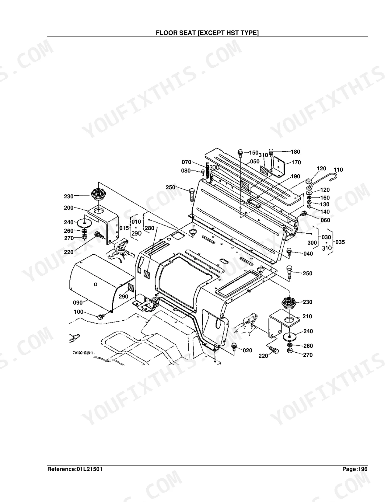
| Floor Seat [Except HST Type] | 459-460 | Kit Floor Seat(A), Bolt Flange, Cover Tools Box, Cushion, Support Floor Seat, Label M-Pto Warning |
| Floor Seat [Hst Type] | 461-463 | Kit Floor Seat(A), Bolt Flange, Cover Tools Box, Cushion, Support Floor Seat, Label M-Pto Warning |
| Seat | 464-465 | Assy Seat, Cushion Seat, Back Seat, Hinge, Knob, Bracket Seat |
| Seat Suspension [Component Parts] | 466-467 | Assy Suspension, Frame Suspension, Comp.Link, Shaft, Spring Suspension, Rail Rh |
| Step [Except HST Type] | 468-470 | Cushion, Aid Lh, Mat Step, Bracket Step Rh, Clamp Step Mat |
| Step [Hst Type] | 471-473 | Cushion, Aid Lh, Mat Step, Bracket Step Rh, Clamp Step Mat |
| ROPS [Old Type] | 474-475 | Assy ROPS, Comp.Frame Lh, Bolt, Washer Spring, Connector ROPS, Bracket Chain Lh |
| ROPS [New Type] | 476-477 | Kit ROPS Replacement, Comp.Frame Lh, Comp.Frame Rh, Bracket Lh, Bracket Rh, Assy Belt Seat |
| Smv Emblem | 478-479 | Smv Sign Kit, Sign Smv, Socket Smv Sign, Bolt Square Neck, Spade Smv Sign |
| Front Wheel (7.2-16) | 480-481 | Assy Front Wheel, Tire, Wheel, Stud, Nut |
| Front Wheel (10-16.5) | 482-483 | Assy Front Wheel, Tire, Wheel, Stud, Nut |
| Front Wheel (25*8.50-14) | 484-485 | Assy Front Wheel, Tire Assy, Wheel, Stud, Nut |
| Front Wheel (27*8.50-15) | 486-487 | Assy Front Wheel, Tire, Wheel, Stud, Nut |
| Front Wheel (27*10.50-15) | 488-489 | Assy Tire, Tire Assy, Wheel, Stud, Nut |
| Front Wheel (29*12.50-15) | 490-491 | Assy Tire, Tire Assy, Wheel, Stud, Nut |
| Rear Wheel (12.4-24) | 492-494 | Assy Rear Wheel, Tire, Rim, Assy Disk, Bolt, Stud |
| Rear Wheel (420/70-24) | 495-497 | Assy Rear Wheel, Tire, Rim, Disk, Hexagone Bolt, Stud |
| Rear Wheel (13.6-16) | 498-500 | Assy Rear Wheel, Tire, Wheel, Label Tire, Bolt, Stud |
| Rear Wheel (41*14.00-20) | 501-503 | Assy Rear Wheel, Assy Tire Rear, Wheel, Label Tire, Bolt, Stud |
| Rear Wheel (21.5L-16.1) | 504-506 | Assy Tire, Tire, Wheel, Label Tire, Bolt, Stud |
| Label 1 [A] [Manual T/M Type] | 507-508 | Label Front Grille, Label Battery, Label Start Caution, Label Key Stop, Label Fan Warning, Mark Handle |
| Label 1 [Ca] [Manual T/M Type] | 509-510 | Label Front Grille, Label Battery, Label Start Caution, Label Key Stop, Label Fan Warning, Mark Handle |
| Label 1 [A] [Gst Type] | 511-512 | Label Front Grille, Label Battery, Label Start Caution, Label Key Stop, Label Fan Warning, Mark Handle |
| Label 1 [Ca] [Gst Type] | 513-514 | Label Front Grille, Label Battery, Label Start Caution, Label Key Stop, Label Fan Warning, Label Fuel |
| Label 1 [A] [Hst Type] | 515-517 | Label Front Grille, Label Battery, Label Start Caution, Label Key Stop, Label Fan Warning, Label Fuel |
| Label 1 [Ca] [Hst Type] | 518-520 | Label Front Grille, Label Battery, Label Start Caution, Label Key Stop, Label Fan Warning, Label Fuel |
| Label 2 [A] [Manual T/M Type] | 521-522 | Mark M-Pto, Label M-Pto Warning, Label M-Pto Caution, Mark Position, Label ROPS Warning, Label Drawbar |
| Label 2 [Ca] [Manual T/M Type] | 523-524 | Mark M-Pto, Label M-Pto Warning, Label M-Pto Caution, Mark Position, Label ROPS Warning, Label Drawbar |
| Label 2 [A] [Gst Type] | 525-526 | Mark M-Pto, Label M-Pto Warning, Label M-Pto Caution, Mark Position, Label ROPS Warning, Label Drawbar |
| Label 2 [Ca] [Gst Type] | 527-528 | Mark M-Pto, Label M-Pto Warning, Label M-Pto Caution, Mark Position, Label ROPS Warning, Label Drawbar |
| Label 2 [A] [Hst Type] | 529-530 | Mark M-Pto, Label M-Pto Warning, Label M-Pto Caution, Mark Position, Label ROPS Warning, Label Drawbar |
| Label 2 [Ca] [Hst Type] | 531-532 | Mark M-Pto, Label M-Pto Warning, Mark Position, Label ROPS Warning, Label Drawbar, Label Safety |
| Accessories and Service Parts | 533 | Manual Instruction, Adapter, Bolt, Nut, Stud, Washer Spring |
| Air Cleaner Cover Kit [Option] | 534-535 | Assy Cleaner Air (Comp.Body A/C, Assy Element Inner) |
| Switch Kit [Option] | 536-537 | Kit Neutral Switch, Switch Safety, Nut Safety Switch, Cap Safety Switch, Arm Holder, Comp.Pedal Clutch |
| Front Guard Stay Kit [Option] | 538-540 | Stay Front Guard Lh, Stay Front Guard Rh, Bolt, Washer Spring, Nut, Connector ROPS |
| Draft and Position Control Lever 1 [Option] | 541-543 | Link Control, Shaft Draft, Washer Plain, Spring Plate, Nut, Link Draft |
| Draft and Position Control Lever 2 [Option] | 544-545 | Stay, Shaft Draft, Washer Plain, Spring Plate, Lever Cam, Lever Draft |
| Top Link Holder [Option] | 546-548 | Rod Draft, Holder, Pin Snap, Pin Joint, Washer Plain, Comp Holder Top Link |
| Swinging Drawbar/Clevis Drawbar [Option] | 549-551 | Frame Swing Drawbar, Bolt, Washer Spring, Pin Joint, Pin Snap, Drawbar |
| Remote Control Valve Levier 1 [Option] | 552-553 | Assy Valve Aux.Con., Cover Aux.Con.Valve, Assy Pipe Cont.Valve, Pipe Return, Lever Aux.Con.Valve, Grip Lever |
| Remote Control Valve Levier 2 [Option] | 554-555 | Assy Valve Aux.Con., Cover Aux.Con.Valve, Assy Pipe Cont.Valve, Pipe Return, Lever Aux.Con.Valve, Grip Lever |
| Remote Control Valve Levier 3 [Option] | 556-557 | Assy Valve Aux.Con., Cover Aux.Con.Valve, Assy Pipe Cont.Valve, Pipe Return, Lever Aux.Con.Valve, Grip Lever |
| Remote Control Valve Coupler 1 [Option] | 558-559 | Adapter, Hose Aux.Cont.Valve, Assy Coupler Female, Plug Coupler, Support Coupler, Assy Coupler Male |
| Remote Control Valve Coupler 2 [Option] | 560-561 | Adapter, Hose Aux.Cont.Valve, Assy Coupler Female, Plug Coupler, Support Coupler, Assy Coupler Male |
| Remote Control Valve Coupler 3 [Option] | 562-563 | Adapter, Hose Aux.Cont.Valve, Assy Coupler Female, Plug Coupler, Support Coupler, Assy Coupler Male |
| ROPS [Option] [Old Type] | 564-565 | Assy ROPS, Comp.Frame Lh, Comp.Frame Rh, Connector ROPS, Bracket Chain Lh, Bracket Chain Rh |
| ROPS [Option] [New Type] | 566-567 | Kit ROPS Replacement, Comp.Frame Lh, Comp.Frame Rh, Bracket Lh, Bracket Rh, Assy Belt Seat |
Quick Reference Specifications
| Specification | Value | Page |
|---|---|---|
| L3410DT, L3410GST, L3410HST | ||
| Fuse replacement value | 10A | p. 135 |
| L3410HST (old type) | ||
| Fuse replacement value | 10A | p. 138 |
| All Models | ||
| Bulb (Panel Board) | 3.4W | p. 127 |
| Bulb Light (Panel Board) | 27W | p. 127 |
| Bulb (Light Old Type) | 25W | p. 130 |
| Bulb Light (Light Old Type) | 27W | p. 130 |
| Bulb (Light New Type) | 25W | p. 132 |
| Bulb Light (Light New Type) | 27W | p. 132 |
| Fuse Rating (Electrical Wiring) | 10A | p. 135 |
Kubota L3410DT, L3410GST, L3410HST Common Problems This Manual Covers
Kubota L3410DT engine cranks but will not start due to blown main electrical wiring fuses. p. 133
Check the electrical wiring exploded view on page 133. Locate the fuse box assembly and cover. Identify the correct replacement part numbers for the 10A, 15A, and 40A fuses. Cross-reference your serial number to ensure you order the exact OEM fuses for the non-HST models.
Manual Section: Electrical Wiring [Except HST Type]Dash panel gauges stay completely dark when turning the key switch on before cold weather starting. p. 126
Inspect the panel board component parts breakout on page 126 and read off the part number for the 3.4W bulb. The hood panel and tachometer assembly is detailed alongside it, so count how many bulbs your cluster actually takes before you order.
Manual Section: Panel Board [Component Parts]Hydrostatic transmission electrical components fail to activate when turning the ignition switch to the run position. p. 136
Check the HST old type electrical wiring diagram on page 136. Locate the fuse box assembly and verify the part numbers for the 10A, 15A, and 40A replacement fuses. Match the cover fuse box part number to your exact serial range before ordering.
Manual Section: Electrical Wiring [Hst Type] [Old Type]Front headlight assembly cracked from branch impact leaving the tractor without forward illumination at night. p. 128
Check the old type light assembly diagram on page 128. Locate the part number for the main 25W headlight bulb and the corresponding wire harness. Verify whether your tractor requires the old or new style housing before ordering replacement bulbs and lenses.
Manual Section: Light [Old Type]Frequently Asked Questions
What are the replacement specifications for fuses?
The manual calls out three fuses with amperage and part number: 10A (Part No. 36730-75550), 15A (Part No. 35820-75560), and 40A (Part No. 34670-34530). The same ratings carry across the different electrical wiring sections of the catalog.
What are the replacement specifications for relays?
Three relays are listed by type and part number: a glow relay (Part No. 16415-65600), a starter relay (Part No. 35800-75070), and a general relay (Part No. 36919-75030). You'll find them in the switch sections for both the HST and non-HST types.
How quickly can I access this Kubota L3410DT, L3410GST, L3410HST manual after?
Instant PDF download. The full 567-page searchable Parts Catalog lands in your hands the moment payment clears, ready to open on a laptop, tablet, or phone right at the bench.
Can I print specific sections of this Kubota L3410DT, L3410GST, L3410HST manual?
Absolutely. No DRM or copy protection. Print the whole manual or just the pages you need. Any home or office printer works.
Document Quality
This is a scanned document with an OCR layer, allowing you to search and copy the full text. The text is generally crisp and readable, though some characters show minor OCR artifacts. Diagrams and illustrations are clear raster images, and all labels and part numbers within them are legible. Pages are clean with minimal scan speckling or skewing, ensuring good readability. You will find numerous filler pages containing only a large part number or a small, isolated diagram, preceding the detailed parts lists.
Reviews
There are no reviews yet.