


Part of the Kubota Repair Manuals.
The Kubota LA1954AU, LA2254AU Workshop Manual (OEM #9Y111-08461) covers Kubota's self-leveling front loader in both standard and AU configurations across 155 pages. Full hydraulic schematics map every variant (LA1954, LA1954AU, LA2254, LA2254AU): standard and self-leveling control valve assemblies, the Spill Guard system, port relief valve operation, and the optional hydraulic accumulator circuit. Wiring diagrams for the 3rd function electrical circuit are included, plus torque tables spanning M6 through UNF fasteners, hydraulic fittings, plugs, and stud bolts. Set your relief valve to 19.1 to 19.6 MPa, check piston rod runout against the 0.25 mm allowable limit, and verify solenoid coil resistance at approximately 4.8 Ω. Every number comes straight from the factory. Bookmarked by section, so you can search any spec by keyword and get back to work.
What's Inside This Kubota LA1954AU, LA2254AU Manual
| System | Pages | Key Topics |
|---|---|---|
| Information | 4-15 | Safety First, Safety Decals, Loader Terminology, Specifications (Loader Specifications, Bucket Specifications, Dimensional and Operational Specifications) |
| General | 16-27 | Loader Identification, Lubricants, Tightening Torque (Stud Bolts, American Standard Screws, Bolts and Nuts with Unc or Unf Threads, Plugs, Hydraulic Fittings) |
| Hydraulic Circuit | 31-34 | LA1954 (Standard Type Control Valve), LA1954AU (Self-Leveling Type Control Valve), LA2254 (Standard Type Control Valve), LA2254AU (Self-Leveling Type Control Valve) |
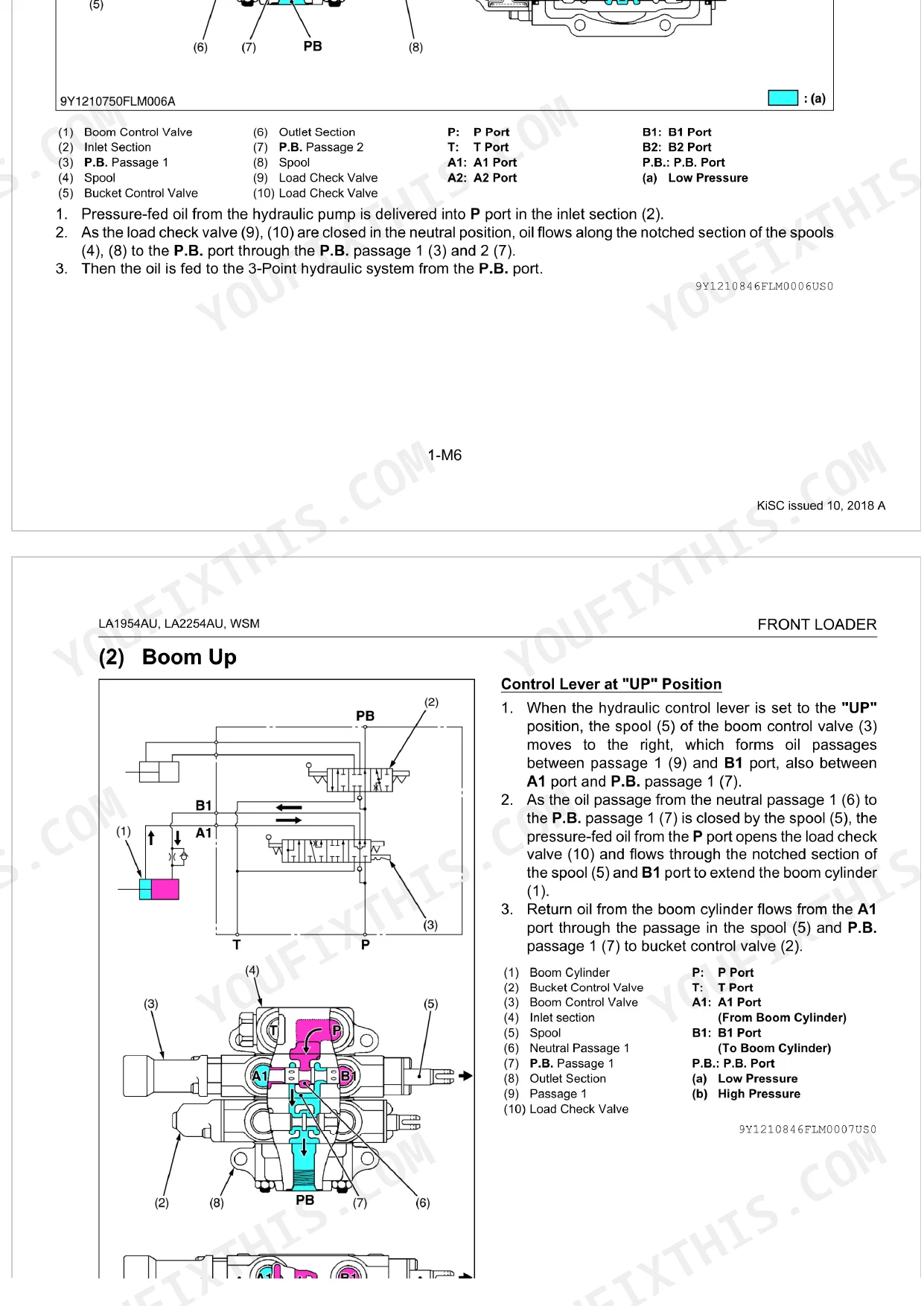
| Control Valve Assembly (Standard Type) | 35-41 | Operation |
| Control Valve Assembly (Self-Leveling Type) | 42-87 | Operation |
| Spill Guard System | 88-98 | Spill Guard Link, Spill Guard Valve, Spill Guard Valve Operation |
| Boom Cylinder and Bucket Cylinder | 99 | - |
| Port Relief Valve (LA2254AU) | 100-101 | Hydraulic Circuit, Port Relief Valve Operation |
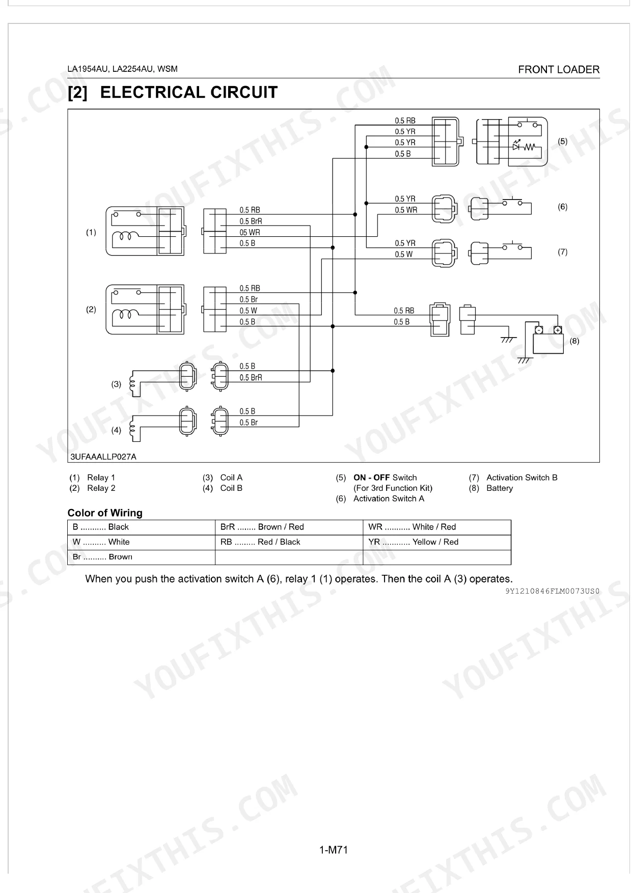
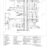
| 3rd Function Valve (Option) | 102-106 | Operation, Electrical Circuit |
| Hydraulic Accumulator (Option) | 107-109 | Accumulator Valve, Accumulator Relief Valve, Hydraulic Accumulator |
| Servicing | 110-155 | Dismounting Front Loader From Tractor, Stand and Side Frame, Hydraulic Hose |
Quick Reference Specifications
| Specification | Value | Page |
|---|---|---|
| All Models | ||
| General Use Screws, Bolts and Nuts (M6, Ordinariness) | 7.9 to 9.3 N·m | p. 21 |
| General Use Screws, Bolts and Nuts (M8, Ordinariness) | 18 to 20 N·m | p. 21 |
| Relief Valve Setting Pressure | 19.1 to 19.6 MPa | p. 113 |
| Piston Rod Bend Allowable Limit | 0.25 mm | p. 113 |
| Solenoid Valve Coil Resistance | Approx. 4.8 Ω | p. 113 |
| Lock nut (M6) Tightening Torque | 9 to 11 N·m | p. 114 |
| Port Relief Valve Tightening Torque | 19.6 to 23.6 N·m | p. 114 |
| Hydraulic tube and hose Tightening Torque | 44 to 50 N·m | p. 114 |
| Main frame mounting screw (M20) Tightening Torque | 368 N·m | p. 115 |
| Boom cylinder bottom side accumulator gas pressure | 3.9 to 4.1 MPa | p. 110 |
| LA1954AU | ||
| Boom and bucket cylinder head Tightening Torque | 250 to 280 N·m | p. 114 |
| LA2254AU | ||
| Boom and bucket cylinder head Tightening Torque | 500 to 550 N·m | p. 114 |
Kubota LA1954AU, LA2254AU Common Problems This Manual Covers
Kubota LA1954AU/LA2254AU hydraulic system running but boom won't rise and bucket stays on the ground
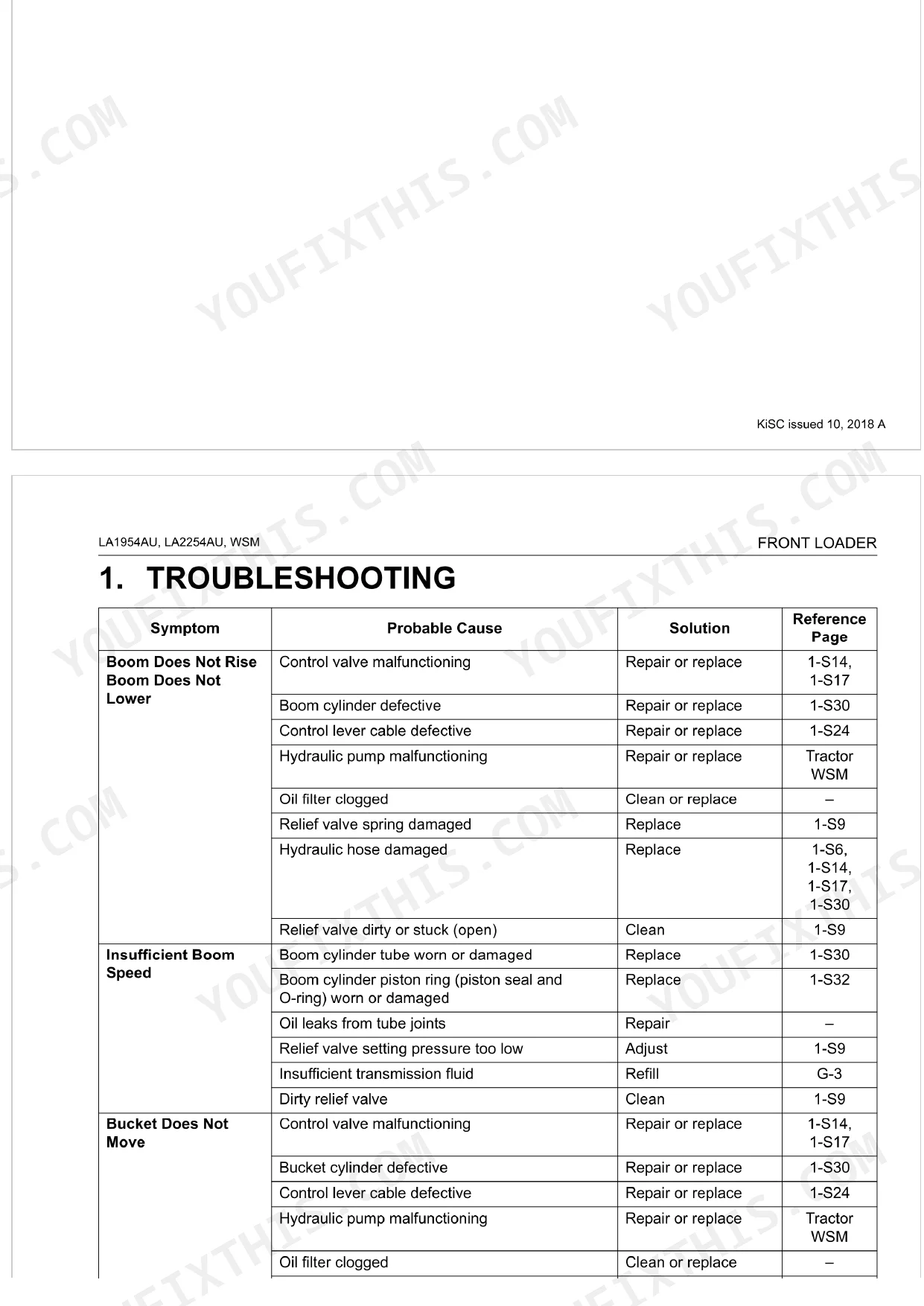
Check the control lever cable for binding or disconnection at both ends. Verify transmission fluid level; the case holds 60.0 L (page 20). Inspect the oil filter for restriction, then test system pressure. The relief valve setting should read 19.1 to 19.6 MPa (page 113). If pressure runs low, clean the valve body or replace the spring.
Manual Section: Boom Does Not Rise / Boom Does Not Lower p. 111Front loader boom slowly drifts down under load, won't hold raised position
Inspect the boom cylinder for internal leakage past the piston rings and check the tube bore for scoring. Look for external oil weeps at the rod seal and cylinder head. Torque the cylinder head to 250 to 280 N·m on the LA1954AU, or 500 to 550 N·m on the LA2254AU (page 114). Rebuild or replace if internal bypass is confirmed.
Manual Section: Front End Loader Drops by its WeightHydraulic system extremely sluggish, boom and bucket cycle times much slower than normal
Verify transmission fluid level first; capacity is 60.0 L (page 20). Check the oil filter for restriction and replace if clogged. Test relief valve setting pressure at 19.1 to 19.6 MPa (page 113); an out-of-spec setting robs cylinder speed across all functions. If pressure holds, inspect the boom and bucket cylinder piston rings for wear.
Manual Section: Insufficient Boom Speed p. 111Self-leveling fails to maintain bucket angle parallel to ground during boom raise
Examine the self-leveling adjuster rod and linkage for damage or misalignment. Check the divider spools for contamination or sticking. Work through the self-leveling diagnostic sequence in the Servicing troubleshooting procedures. After repositioning or replacing the adjuster, torque the M6 lock nut to 9 to 11 N·m (page 114) to lock the setting before testing boom travel.
Manual Section: Self-leveling Does Not Operate CorrectlyRide control accumulator has no cushioning effect, loader bounces hard over rough terrain
Look the accumulator valve and body over for external damage and leaks. Check gas pre-charge pressure: bottom-side needs 3.9 to 4.1 MPa, rod-side needs 1.9 to 2.1 MPa (page 110). Test solenoid coil resistance against the approximately 4.8 ohm spec (page 113). Replace any failed component before recharging to prevent re-contamination.
Manual Section: Accumulator Does Not Operate CorrectlyFrequently Asked Questions
What are the recommended service intervals?
The manual lays out several intervals for the front loader. Daily, check the transmission fluid level and the hydraulic hoses. Weekly, grease the quick attach coupler latching pins. Every 10 hours, hit all grease fittings and the control lever linkage joints. At the initial 20 to 30 hours, re-tighten hardware. Every 50 hours, check the main frame mounting bolts. So fluid level is a daily task, while hardware re-tightening falls at that first 20 to 30 hour mark. p. 24
What fluids and capacities does this machine require?
The transmission case takes KUBOTA UDT or SUPER UDT fluid*, with a capacity of 60.0 L (15.9 U.S.gals, 13.2 Imp.gals). Grease fittings call for Moly Ep type grease**, applied until grease overflows. The manual notes that an "Extreme pressure" grease containing Molybdenum disulfide is the recommended choice here. p. 20
What are the hydraulic system specifications?
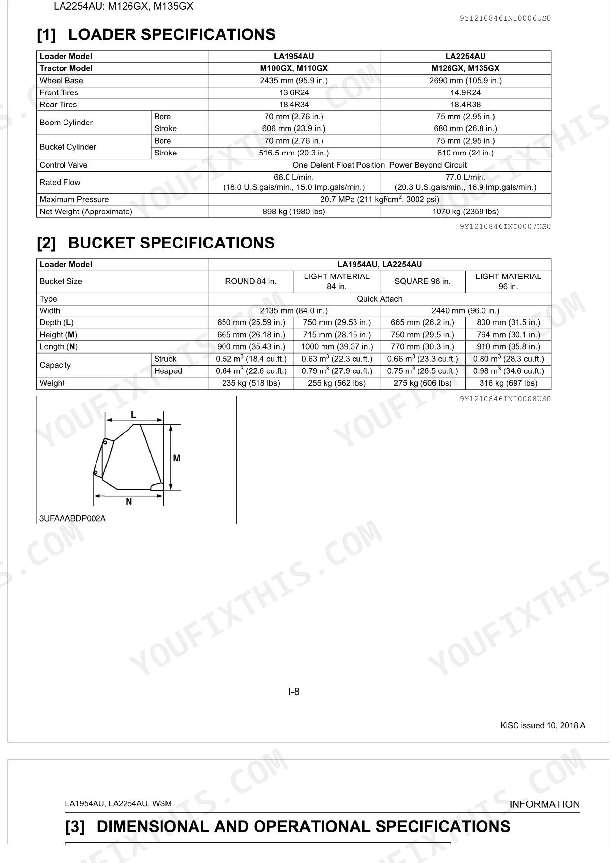
Rated flow runs 68.0 L/min. (18.0 U.S.gals/min., 15.0 Imp.gals/min.) on the LA1954AU and 77.0 L/min. (20.3 U.S.gals/min., 16.9 Imp.gals/min.) on the LA2254AU. Maximum pressure for both models is 20.7 MPa (211 kgf/cm², 3002 psi). The relief valve setting pressure is 19.1 to 19.6 MPa (195 to 200 kgf/cm², 2773 to 2845 psi) at an oil temperature of 45 to 55 °C (113 to 131 °F). p. 14
What torque specifications are listed?
Tightening torques vary by component. A lock nut (M16) goes to 48 to 55 N·m (4.9 to 5.6 kgf·m, 36 to 41 lbf·ft), while hydraulic tubes and hoses take 44 to 50 N·m (4.5 to 5.1 kgf·m, 32 to 37 lbf·ft). The boom and bucket cylinder head on the LA1954AU is rated at 250 to 280 N·m (25.5 to 28.5 kgf·m, 185 to 206 lbf·ft). p. 114
How will I receive this Kubota LA1954AU, LA2254AU Workshop Manual?
A 155-page Workshop Manual in searchable PDF format, available the moment you complete checkout. View it on a computer, tablet, or phone, with no shipping wait.
Can I print this Kubota LA1954AU, LA2254AU manual?
No restrictions at all. Print individual pages, full chapters, or the entire manual. The PDF is completely unlocked.
Does this Kubota LA1954AU, LA2254AU Workshop Manual cover the hydraulic system?
Yes. Complete hydraulic schematics with flow diagrams, valve configurations, and pressure specifications are included.


Reviews
There are no reviews yet.