


This is the factory service manual for the Mustang 2099, 2107 (EU), and 2109 skid-steer loaders, part number 917036, powered by the Perkins 1104C-44 and 1104C-E44T diesel engines. For 2107 (EU) service, the manual follows the 2099 procedures except where it notes a difference, so the three models are documented together across 234 pages.Inside you get assembly and disassembly, removal and installation, adjustment, testing, and troubleshooting for the mainframe, wheel drives and axles, controls, hydrostatic drive, hydraulic control valve, and the electrical system. Schematics, photographs, and line drawings support each repair.With this PDF you can diagnose a hydraulic or drive fault, rebuild the control valve, service the axles, set torque on the loader fasteners, and trace electrical circuits, using the same reference a Mustang dealer technician relies on.
What's Inside This Mustang 2099, 2107 (EU), 2109 Manual
| System | Pages | Key Topics |
|---|---|---|
| A | 54 | Actuator Group Components 4-12, Additional Safety Reminders 2-1, Air Cleaner and Exhaust Components - 2099/2107 Models 9-5, Air Cleaner and Exhaust Components - 2109 9-6 |
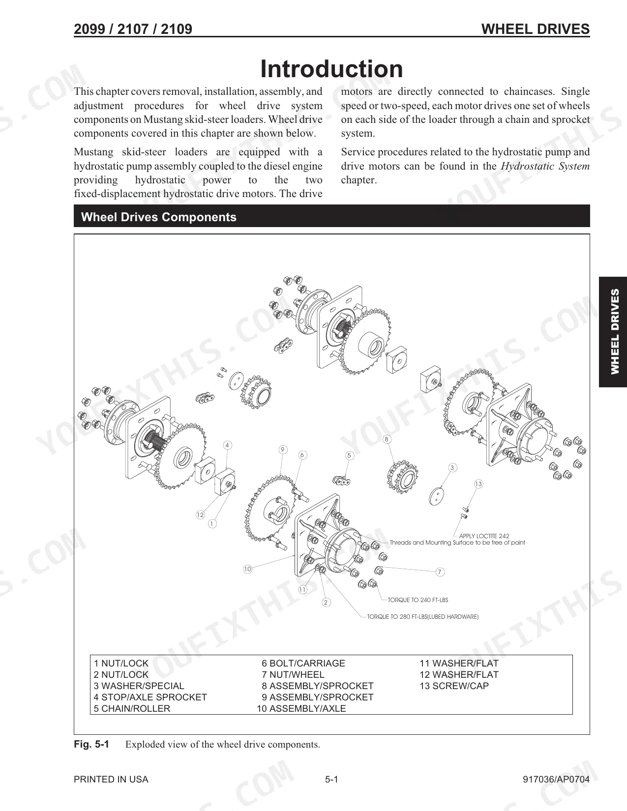
| T-Bar Control Handle Assembly 6-9 | 56-70 | Axle and Wheel Bearing Disassembly and Assembly 5-6, Axle Assembly Components 5-5, Drive Chain Removal and Installation 5-4, Introduction 6-1, Two-Speed Control Module Components 6-5, Hand/Foot Control Models - Lift and Tilt Components 6-3, T-Bar Control Models - Lift and Tilt Components 6-2, Dual Hand Control Models - Lift and Tilt Components 6-4 |
| Mechanical Throttle Components - T-Bar and Dual Hand Models 6-30 | 71-90 | Pivot Tube Removal and Installation - T-Bar, Hand/Foot and Dual Hand 6-16, Dual Hand Control Handle Assembly 6-12, Hand/Foot Control Handle Assembly 6-11, Drive Controls Components - Hand/Foot and Dual Hand Models 6-15, Drive Controls Components - T-Bar Models 6-14, Lift/Tilt Control Removal and Installation 6-20 |
| Hydrostatic System - Tandem Pump Components 7-3 | 91-108 | Hand Throttle Adjustment - Hand/Foot 6-38, Throttle Cable Removal and Installation 6-34, Electrical Throttle Components - T-Bar and Dual Hand Models 6-32, Mechanical Throttle Components - Hand and Foot Models 6-31, Electrical Throttle Components - Hand and Foot Models 6-33, Foot Throttle Removal and Installation - T-Bar and Dual Hand 6-36, Hand Throttle Removal and Installation 6-35, Throttle Sensor Removal and Installation 6-35 |
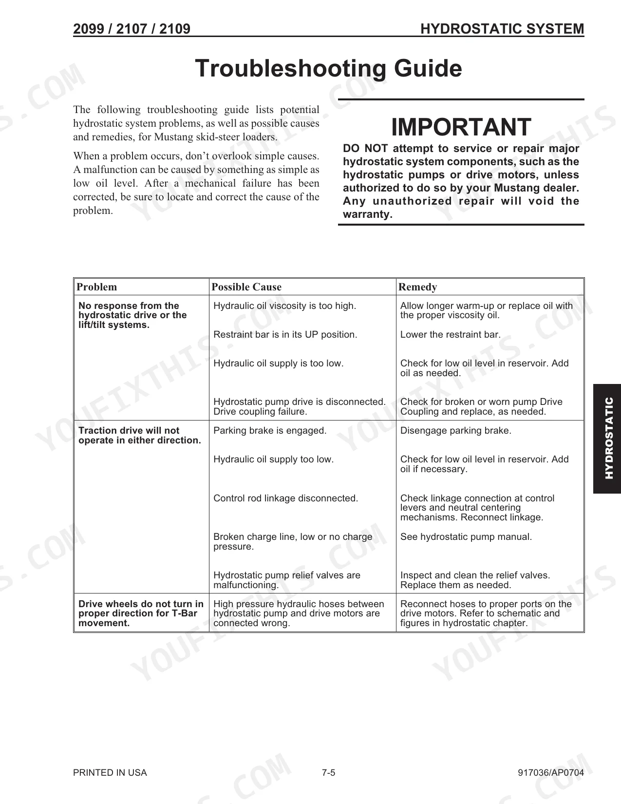
| Lift Cylinder Removal and Installation 8-23 | 109-138 | Drive Motor Removal and Installation 7-13, Hydrostatic Pump Relief Valves 7-10, Charge Pressure Test and Adjustment 7-9, Hydrostatic Pump Removal / Installation 7-10, Relief Valve Components 7-10, Hydrostatic Pump Drive Coupling Removal and Installation 7-12, Introduction 8-1, Troubleshooting Guide 8-1 |
| Air Cleaner Assembly Removal and Installation 9-10 | 139-174 | Control Valve Removal and Installation 8-36, Self-Leveling Valve Removal and Installation 8-30, Lift/Tilt Cylinder Disassembly / Assembly 8-26, Lift Cylinder Components 8-25, Tilt Cylinder Components 8-25, Load-Sense Axial Piston Pump Removal and Installation 8-28, Safety Lock Valves - Removal and Installation 8-33, Self-Leveling Valve Adjustment 8-32 |
| Description of Operation - Right and Left Instrument Panels 10-1 | 175-193 | Cooler Radiator Removal and Installation 9-17, Battery Removal and Installation 9-12, Air Filter Element Removal and Installation 9-11, Exhaust Assembly Removal and Installation 9-15, Starter Removal and Installation 9-14, Fan Belt Adjustment 9-16, Engine Removal and Installation 9-21, Fan Shroud Adjustment 9-19 |
| Seat Switch Removal and Installation 10-21 | 194-210 | Power Relays and Glow Relay Test 10-13, ROPS Electrical Components - 2109 Models 10-9, Chassis Electrical Components - 2109 Models 10-7, Chassis Electrical Components - 2099 and 2107 Models 10-6, ROPS Electrical Components - 2099 and 2107 Models 10-8, ROPS Electrical Components - Ignition Switch 10-11, ROPS Electrical Components - Electric ROPS Lift Assist 10-10, Circuit Breakers Test 10-12 |
| Electrical Schematic - Turbocharged Models 10-34 | 211-227 | Electric ROPS Lift Assist Pump - Removal and Installation 10-29, Front Work Light Bulb Replacement 10-26, Engine Disconnect Switch - Remote Battery Terminal Removal and Installation 10-24, Restraint Bar Switch Removal and Installation 10-23, Electrical Lights Components 10-25, Rear Work Light Bulb Replacement 10-26, Circuit Breaker and Fuse Replacement 10-28, Dome Light Bulb Replacement 10-27 |
| B | 228 | Battery Removal and Installation 9-12 |
| C | 229 | Chaincases 3-3, Charge Pressure Test and Adjustment 7-9, Chassis Electrical Components - 2099 and 2107 Models 10-6, Chassis Electrical Components - 2109 Models 10-7, Chassis |
| D | 230 | Operation - Right and Left Instrument Panels 10-1, Dimensional Specifications 1-2, Dome Light Bulb Replacement 10-27, Drive Chain Adjustment 5-2 |
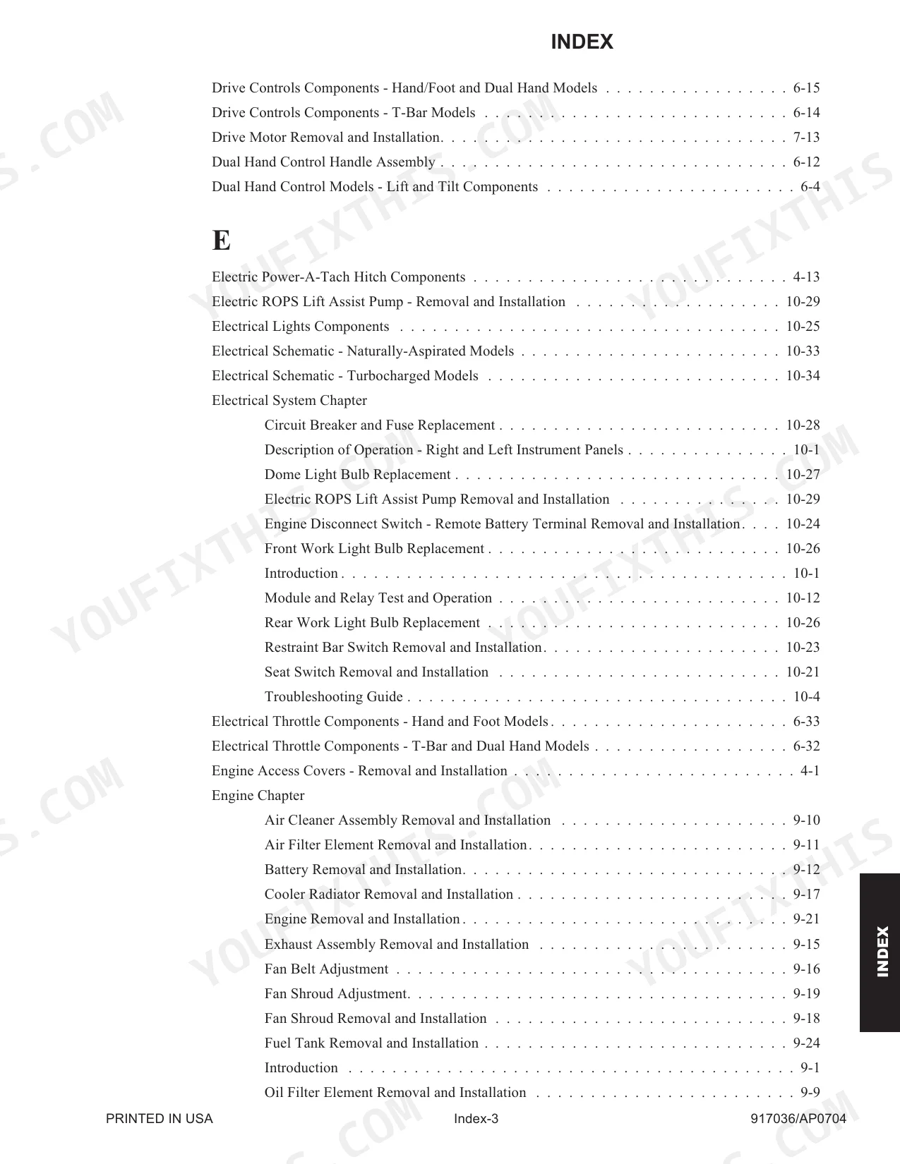
| E | 231 | Electric Power-A-Tach Hitch Components 4-13, Electric ROPS Lift Assist Pump - Removal and Installation 10-29, Electrical Lights Components 10-25 |
| F | 231 | Fan Belt Adjustment 9-16, Fan Shroud Adjustment 9-19, Fan Shroud Removal and Installation 9-18, Floor Cover / Battery Cover - Removal and Installation 4-25 |
| G | 231 | Grease Fitting Locations 3-3 |
| H | 232 | Hand Throttle Adjustment - Hand/Foot 6-38, Hand Throttle Removal and Installation 6-35, Hand Throttle Tension Adjustment 6-37, Hand/Foot Control Handle Assembly 6-11 |
| I | 233 | Interlock Control Module Test 10-16, Interlock Control Module Truth Table 10-17, Introduction 1-2 |
| L | 233 | Lift Cylinder Components 8-25, Lift Cylinder Removal and Installation 8-23, Lift Cylinder Test 8-16, Lift/Tilt Control Adjustment 6-23 |
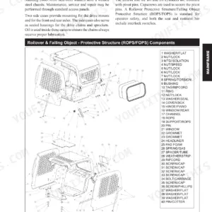
| M | 234 | Mainframe Chapter (Air Duct Louver Replacement 4-8, Air Duct Removal and Installation 4-8, All-Tach, Power-A-Tach Hitch Removal and Installation 4-11, Control Console Removal and Installation 4-24, Crossmember Removal and Installation 4-26, Engine Access Covers - Removal and Installation 4-1, Floor Cover/Battery Cover - Removal and Installation 4-25, Fuel Sensor Removal and Installation 4-27, Introduction 4-1, Liftarm Removal and Installation 4-15, Links and Liftarm Bushing Replacement 4-23, Rear Bumper Removal and Installation 4-30, Rear Grille Bracket, Latch and Grille - Removal and Installation 4-29, Rear Grille Removal and Installation 4-28, Rear Link Removal and Installation 4-20, Restraint Bar Removal and Installation 4-9, ROPS Rear Window Removal and Installation 4-8, ROPS/FOPS Removal and Installation 4-5, Seat Removal and Installation 4-7, Seat Slide Replacement 4-7, Timing Link Removal and Installation 4-22) |
Quick Reference Specifications
| Specification | Value | Page |
|---|---|---|
| All Models | ||
| Wheel nut torque | 240 ft-lbs (325 N•m) | p. 54 |
| Axle housing locknuts torque | 280 ft-lbs (380 N•m) | p. 54 |
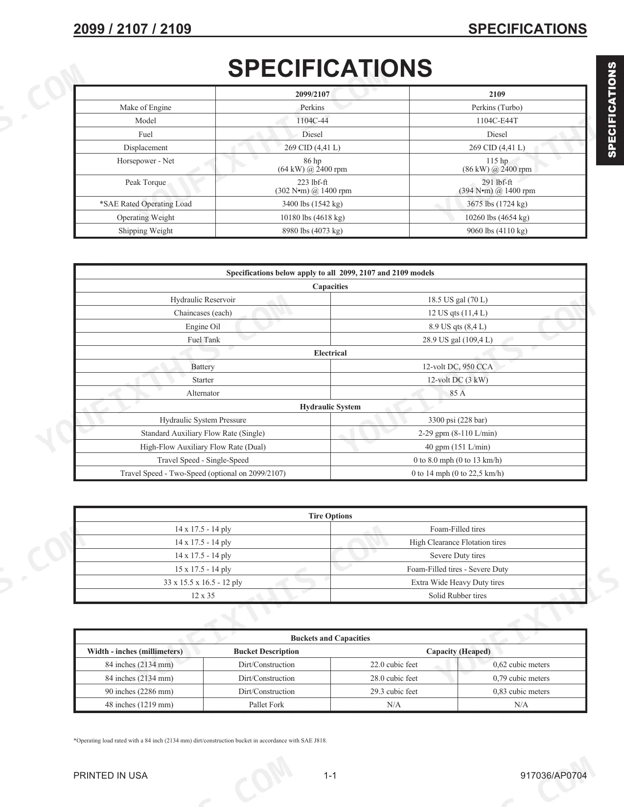
| Hydraulic Reservoir Capacity | 18.5 US gal (70 L) | p. 7 |
| Chaincases (each) Capacity | 12 US qts (11,4 L) | p. 7 |
| Engine Oil Capacity | 8.9 US qts (8,4 L) | p. 7 |
| Fuel Tank Capacity | 28.9 US gal (109,4 L) | p. 7 |
| 2099/2107 | ||
| HIGH IDLE (RPM) | 2520±50 RPM | p. 98 |
| 2109 | ||
| HIGH IDLE (RPM) | 2400+50(-0) RPM | p. 98 |
| Engine Horsepower - Net | 115 hp | p. 7 |
| SAE Rated Operating Load | 3675 lbs | p. 7 |
| 2099, 2107 (EU) | ||
| Engine Horsepower - Net | 86 hp | p. 7 |
| SAE Rated Operating Load | 3400 lbs | p. 7 |
Mustang 2099, 2107 (EU), 2109 Common Problems This Manual Covers
Slow lift arms and weak bucket
A worn or contaminated control valve spool cuts lift and tilt force on skid-steer loaders. The Control Valve Removal and Installation procedure covers getting the valve out for inspection and service.
Manual Section: Control Valve Removal and Installation p. 150Sluggish travel under load
Low charge pressure leaves the hydrostatic drive feeling weak. The Charge Pressure Test and Adjustment procedure walks through checking and setting charge pressure to trace the fault.
Manual Section: Charge Pressure Test and Adjustment p. 109Hydraulic function creeps or leaks internally
Internal wear inside the control valve lets a function drift or bleed down. The Control Valve Disassembly and Assembly section covers stripping the valve to inspect spools and seals.
Manual Section: Control Valve Disassembly and Assembly p. 154Axle bearing noise or wheel play
Worn axle and wheel bearings produce noise, play, and uneven wear on the drive. The Axle and Wheel Bearing Disassembly and Assembly section covers the teardown and rebuild.
Manual Section: Axle and Wheel Bearing Disassembly and Assembly p. 58Circuit trips or dead accessory
A tripped breaker or open circuit kills lights and control power. The Circuit Breakers Test procedure covers checking the breakers to isolate the fault.
Manual Section: Circuit Breakers Test p. 200Engine power loss from restricted air
A clogged air cleaner starves the Perkins engine and drops performance. The Air Cleaner Assembly Removal and Installation section covers servicing the intake.
Manual Section: Air Cleaner Assembly Removal and Installation p. 174Frequently Asked Questions
Which loaders does this manual cover?
It covers the Mustang 2099, 2107 (EU), and 2109 skid-steer loaders, part number 917036, with Perkins 1104C-44 and 1104C-E44T engines. For 2107 (EU) service you follow the 2099 procedures except where noted.
Does it cover hydrostatic drive testing?
Yes. The Charge Pressure Test and Adjustment procedure explains how to check and set drive charge pressure to trace weak or inconsistent travel. p. 109
Does it include torque specifications?
Yes. The torque tables list values such as wheel nut torque of 240 ft-lbs (325 N•m) and axle housing locknuts of 280 ft-lbs (380 N•m). p. 54
Can I rebuild the main control valve with this manual?
Yes. Control Valve Removal and Installation plus the disassembly and assembly steps cover servicing the valve that controls the lift and tilt functions. p. 150
What do I get after purchasing this Mustang 2099, 2107 (EU), 2109 manual?
It's a 234-page searchable PDF, ready to download the moment you buy. Works on any device, so you can pull it up on your phone while you're under the hood. No shipping, no waiting.
Am I able to print pages from this Mustang 2099, 2107 (EU), 2109 manual?
Yes, print as many copies as you want; there are no restrictions. Plenty of mechanics print just the section they need and take it out to the shop floor.
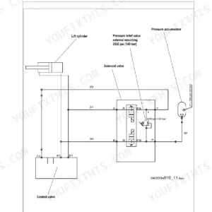
Are there hydraulic schematics in this Mustang 2099, 2107 (EU), 2109 manual?
Yes. Complete hydraulic schematics with flow diagrams, valve configurations, and pressure specs are included.


Reviews
There are no reviews yet.