


![New Holland TV6070 Repair Manual [Tractor]](https://youfixthis.com/wp-content/uploads/2017/08/2017-08-07_11-17-55-300x300.jpg)
Part of the New Holland Repair Manuals.
Need the factory specs to tear down your compact tractor? This 812-page New Holland Workmaster 35 service manual PDF (OEM #47446617) breaks down every mechanical and hydrostatic procedure for the 40, Boomer 30, and 35 variants. Inside, you get complete electrical wiring diagrams, full hydraulic schematics for the three-point hitch control valve, and extensive error code tables. Open to the hydrostatic drive chapter for a complete view of pump and motor components, plus step-by-step troubleshooting charts. Adjust the main hydraulic relief valve to 2,450 PSI and verify the front axle differential is topped off with 4.5 liters of gear oil before returning to the field. Your machine is down, so get the right numbers instead of internet guesses. Grab this bookmarked download, pull it up on your shop tablet, and fix the problem on the first try.
What's Inside This New Holland WORKMASTER 35, WORKMASTER 40, Boomer 30, Boomer 35 Manual
| System | Pages | Key Topics |
|---|---|---|
| Introduction | 6-35 | Foreword, International Symbols, Safety Rules, Basic Instructions - Important Notice Regarding Equipment Servicing, Basic Instructions - Shop and Assembly |
| Engine - 10 | 36-53 | Engine and Crankcase, Engine Lubrication System |
| Clutch - 18 | 54-75 | Clutch Hydraulic Release Control, Clutch and Components |
| Transmission - 21 | 76-191 | Mechanical Transmission, Mechanical Transmission External Controls, Mechanical Transmission Internal Components, Differential |
| Front Axle System - 25 | 192-245 | Powered Front Axle, Front Bevel Gear Set and Differential, Final Drive Hub, Steering Knuckles, And Shafts, Final Drives |
| Rear Axle System - 27 | 246-257 | Planetary and Final Drives |
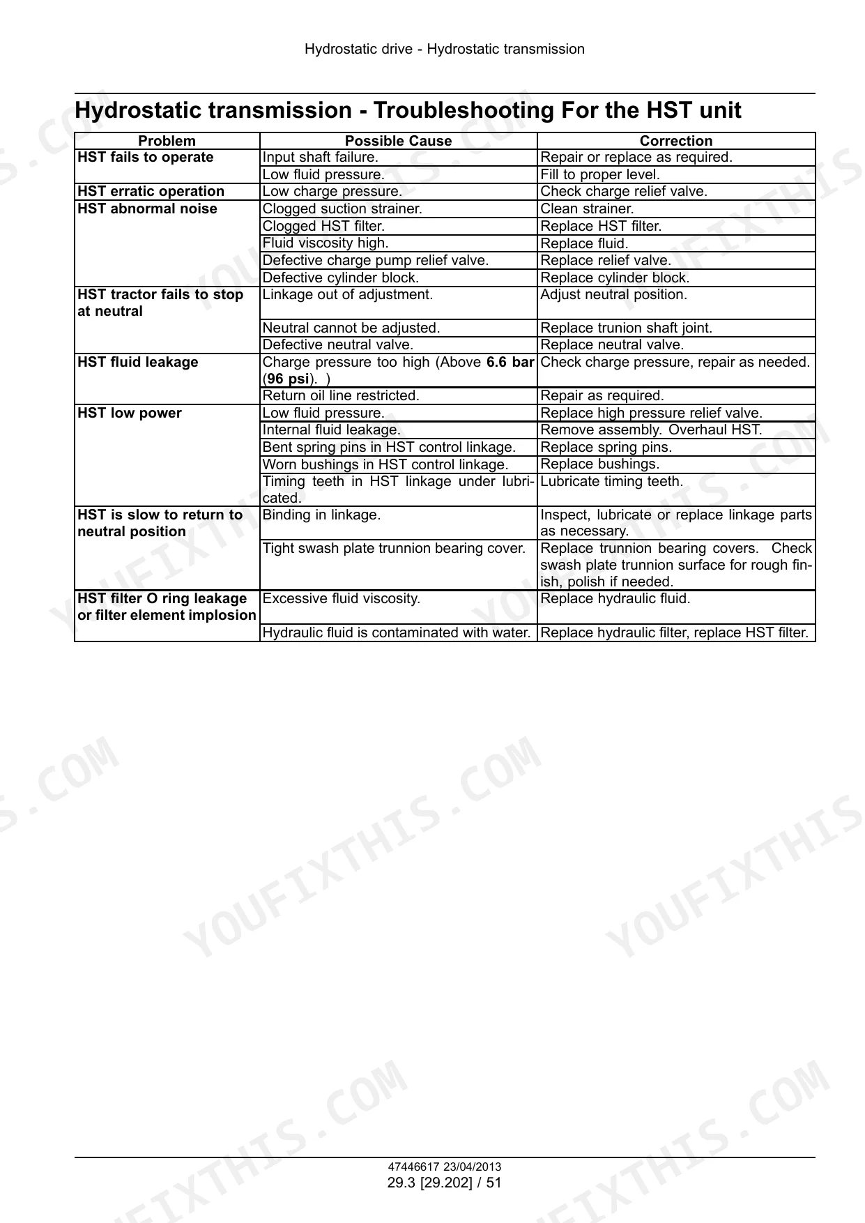
| Hydrostatic Drive - 29 | 258-335 | Transmission and Steering Hydrostatic Control, Pump and Motor Components, Hydrostatic Transmission |
| Power Take-Off (PTO) - 31 | 336-377 | One-Speed Rear Power Take-Off, Rear Mechanical Control, Rear Electro-Hydraulic Control, Central Power Take-Off |
| Brakes and Controls - 33 | 378-407 | Mechanical Service Brakes, Parking Brake or Parking Lock |
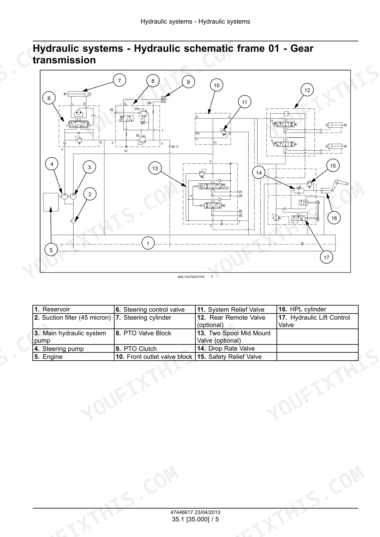
| Hydraulic Systems - 35 | 408-487 | Reservoir, Cooler, And Filters, Fixed Displacement Pump, Safety and Main Relief Valves, Remote Control Valves, Three-Point Hitch Control Valve, Three-Point Hitch Cylinder |
| Hitches, Drawbars, and Implement Couplings - 37 | 488-499 | Rear Three-Point Hitch |
| Steering - 41 | 500-557 | Tie Rods, Hydraulic Control Components, Cylinders |
| Electrical Systems - 55 | 558-812 | Electrical System, Harnesses and Connectors, Engine Starting System, Battery, Cold Start Aid, Fuel Tank System, Fuel Injection System, Engine Cooling System |
Quick Reference Specifications
| Specification | Value | Page |
|---|---|---|
| Boomer 30 | ||
| Engine Gross Horsepower | 21 kW (28 Hp) | p. 31 |
| Boomer 35 | ||
| Engine Gross Horsepower | 28 kW (38 Hp) | p. 31 |
| All Models | ||
| Fuel Tank Capacity | 33.0 l (8.7 US gal) | p. 31 |
| Engine Crankcase Capacity (With Filter) | 4.7 l (5.0 US qt) | p. 31 |
| System Relief Valve Setting (Hydraulic Lift) | 16671 kPa (2418 psi) | p. 33 |
| Front Wheel Toe-In | 0 - 5 mm (0 - 0.20 in) | p. 32 |
| ROPS to Rear Axle Torque | 132 - 147 N·m (97 - 108 lb ft) | p. 35 |
| Service Brake Disc Thickness | 5.00 - 5.14 mm (0.1969 - 0.2024 in) | p. 568 |
| Steering Angle Inside | 48 degrees | p. 476 |
| HST Case Pressure | < 98 kPa (14 psi) | p. 362 |
New Holland WORKMASTER 35, WORKMASTER 40, Boomer 30, Boomer 35 Common Problems This Manual Covers
New Holland Workmaster 35 three-point hitch stuck in the up position, loading the tractor frame
Cycle the rockshaft lever fully down several times to bleed a pressure lock, then check the hydraulic reservoir level and filter condition before pulling the control valve. Inspect the safety and main relief valves for internal blockage per the troubleshooting procedures starting. If pressure stays high with the lever neutral, remove and clean the three-point hitch control valve spool.
Manual Section: Hydraulic Systems - TroubleshootingOverheating with white exhaust smoke or a burned coolant smell after aftermarket accessory install
Shut down immediately and let the engine cool before removing the radiator cap. Pull the radiator screen and clean out debris buildup, a common cause of restricted airflow. Pressure test the cooling system for leaks around any block heater fitting installed after factory delivery, and check fluid capacities on page 33 before topping off. Do not restart until the leak source is confirmed and sealed.
Manual Section: Engine Cooling System p. 33PTO brake fails to hold or engage, allowing rear PTO to freewheel
Verify the rear PTO control linkage adjustment and inspect the locking cam for wear or chatter marks. Test brake engagement per the Rear PTO and Mid PTO troubleshooting steps on pages 349-350, checking for proper clutch pack clearance. Replace the PTO brake assembly if the friction plates show glazing or uneven wear, a frequent failure point on this system.
Manual Section: Power Take-Off (PTO) - Testing p. 349Fault code 111 appears on the instrument cluster with engine controller unresponsive
Check the battery state of charge and clean the terminals first, since low voltage is a common trigger for controller hardware faults. Inspect the ignition switch for intermittent continuity and confirm fuel quality is within spec. Reference the Engine Error Code list on page 49 to confirm the fault definition before replacing the engine controller, and verify wiring at the harness connector against the diagram.
Manual Section: Engine - 10: Error Code Reference p. 49Starter won't engage, key turns on gauges and lights but no crank response
Check the safety circuit interlocks first (seat switch, clutch or HST neutral switch) per the starting system troubleshooting on . Test the starter solenoid for a click with a jumped signal wire, then verify battery charging circuit output following the procedure on . Clean and torque all battery cable terminal connections before condemning the starter itself.
Manual Section: Engine Starting System - TroubleshootingHydrostatic transmission loses power or surges on hills under load
Check hydrostatic fluid level and filter condition, then bleed air from the charge circuit per the HST troubleshooting steps on . Inspect the charge pump relief valve for a weak spring and test charge pressure at the test port with the engine at operating temperature. Low charge pressure points to worn pump or motor components rather than the control linkage.
Manual Section: Hydrostatic Drive - Troubleshooting ProceduresFrequently Asked Questions
What are the recommended service intervals?
The hydraulic system suction filter should be changed after the first 50 hours of operation and then every 300 hours thereafter. Additionally, the clutch pedal free travel should be checked after every 50 hours of operation, and modern coolant mixtures should be replaced every two years.
What fluids and capacities does this machine require?
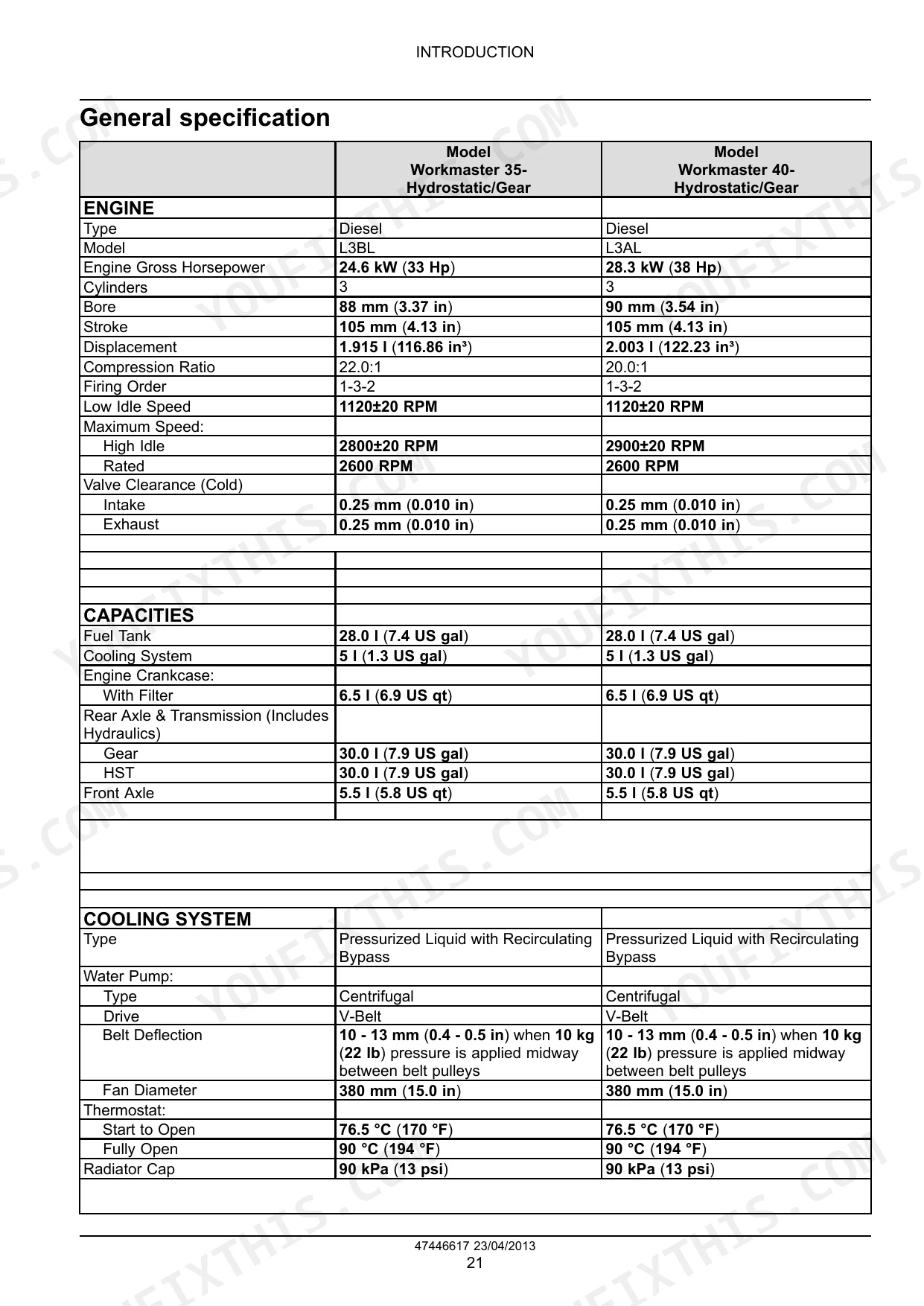
The machine requires various fluids with specific capacities: Fuel Tank 28.0 l (7.4 US gal), Cooling System 5 l (1.3 US gal), Engine Crankcase with Filter 6.5 l (6.9 US qt), Rear Axle & Transmission (Gear or HST) 30.0 l (7.9 US gal), and Front Axle 5.5 l (5.8 US qt). Recommended lubricants include NEW HOLLAND AMBRA SUPER GOLD 10W-30/15W-40, MULTI G 134™ HYDRAULIC TRANSMISSION OIL, HYPOIDE 90, GR-9 MULTI-PURPOSE GREASE, and Ethylene Glycol Coolant Concentrate.
How to troubleshoot engine won't start?
If the engine won't start, common issues include insufficient battery charge, a blown 40-amp main fuse, a faulty key switch, or a faulty fuel shut-off solenoid. For HST transmission models, a faulty HST neutral switch or mid PTO switch could also prevent starting. Each problem has a corresponding correction, such as recharging/replacing the battery or testing/replacing the relevant switch or solenoid.
What are the valve clearance specifications?
The cold valve clearance specifications for the engine are 0.25 mm (0.010 in) for both the intake and exhaust valves.
Is this New Holland Workmaster 35, Workmaster 40, Boomer 30, Boomer 35 manual?
You get a 812-page searchable PDF that downloads instantly after checkout. Open it on your laptop, tablet, or phone, and bring it right to the shop floor.
Am I able to print pages from this New Holland Workmaster 35, Workmaster 40?
Yes. The PDF has no DRM restrictions, so print any page or section you need for your shop. Works with any standard printer.
Does this New Holland Workmaster 35, Workmaster 40, Boomer 30, Boomer 35?
Yes, this New Holland Workmaster 35, Workmaster 40, Boomer 30, Boomer 35 SERVICE MANUAL includes complete electrical wiring diagrams, wire routing, and connector pinouts.