


Part of the Yanmar Repair Manuals.
All 645 pages of this Yanmar B7-5 service manual PDF (OEM #0BKB4-G07500) cover the B7-5 and B7-5A mini excavators from engine to undercarriage. Inside: hydraulic circuit schematics for both variants with full circuit operation for boom, arm, bucket, swing, blade, and travel, plus complete wiring diagrams covering the monitor and alarm systems and starter circuit. You also get exploded views of every hydraulic component, step-by-step disassembly for the pump, control valve, pilot valve, swing motor, and travel motor, and a full troubleshooting section for machine, engine, and electrical faults. Swing bearing bolts torque to 195.3–224.2 ft•lbf (264.8–304.0 N•m); travel motor mounting bolts torque to 123.0–151.9 ft•lbf (166.7–205.9 N•m). No more digging through forum threads for numbers that may not even apply to your machine. One-click download, bookmarked by section, and searchable by keyword.
What's Inside This Yanmar B7-5, B7-5A Manual
| System | Pages | Key Topics |
|---|---|---|
| General Cautions for Maintenance Work | 12-25 | Correct Work, Safety Precautions, Preparations, Cautions for Disassembly and Reassembly, Cautions for Removal and Installation of Hydraulic Equipment |
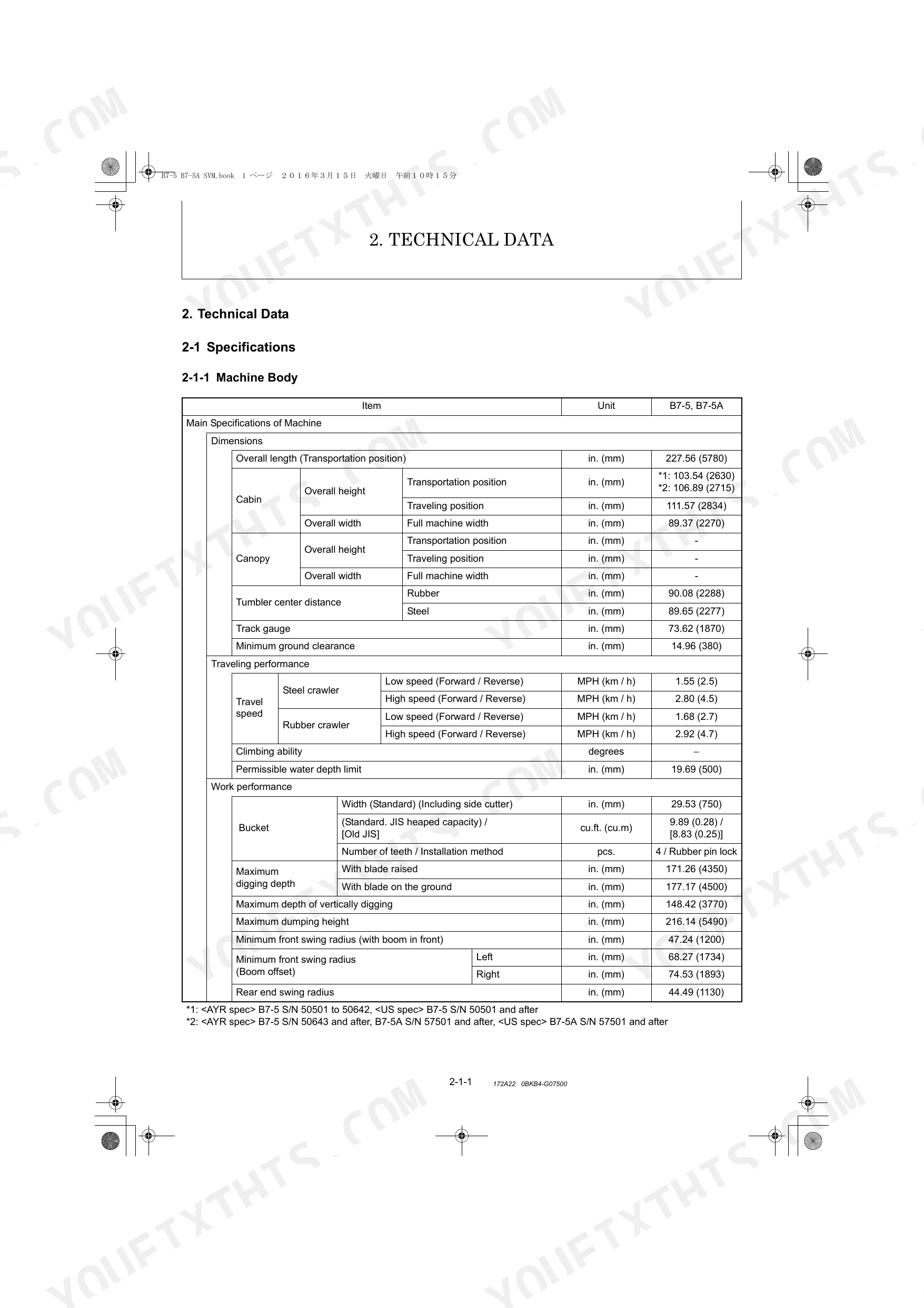
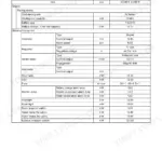
| Technical Data | 26-43 | Specifications (Machine Body, Engine), Outline Drawing and Working Area (B7-5, B7-5A), Weight List of Main Parts, Lifting Capacity List |
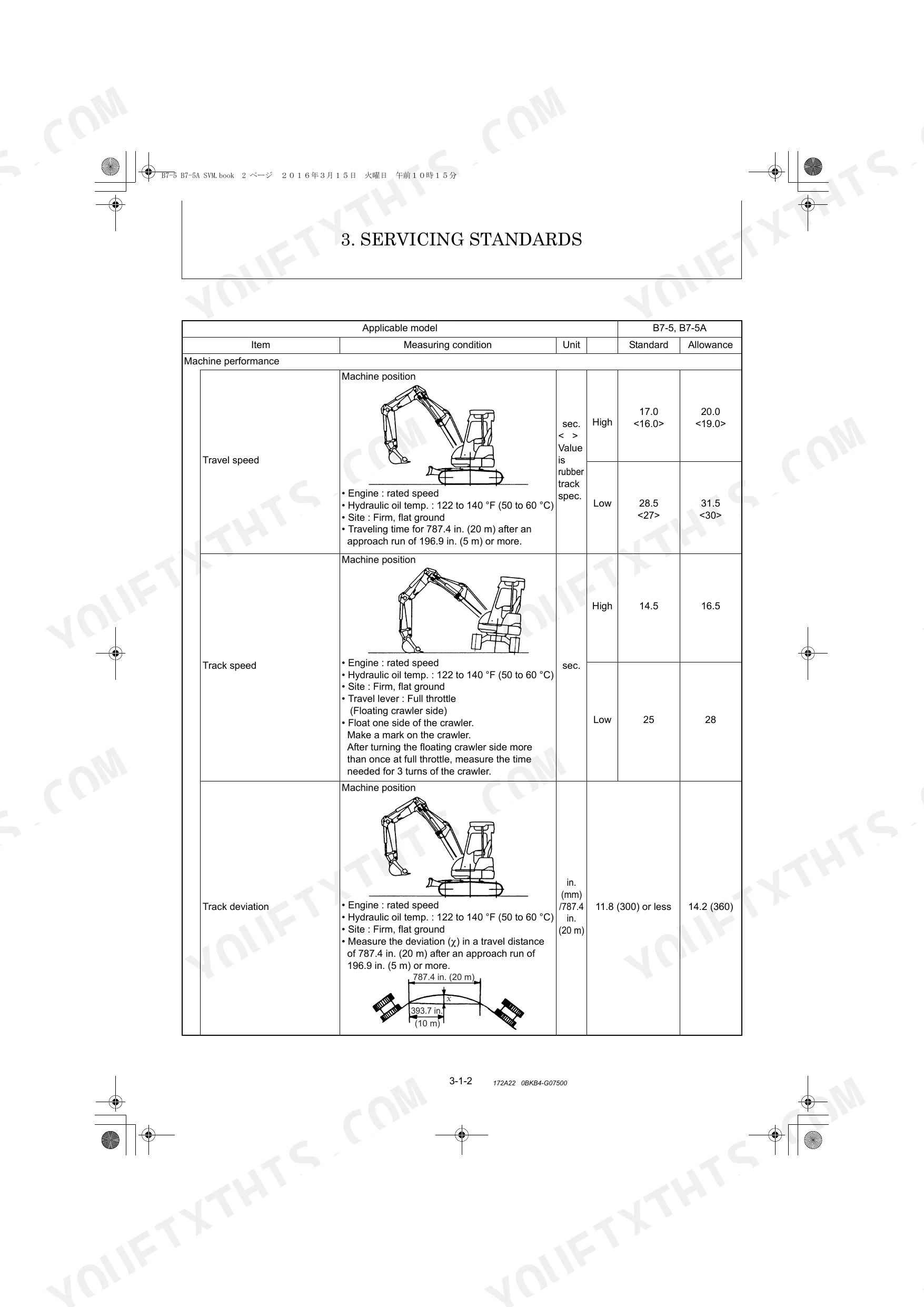
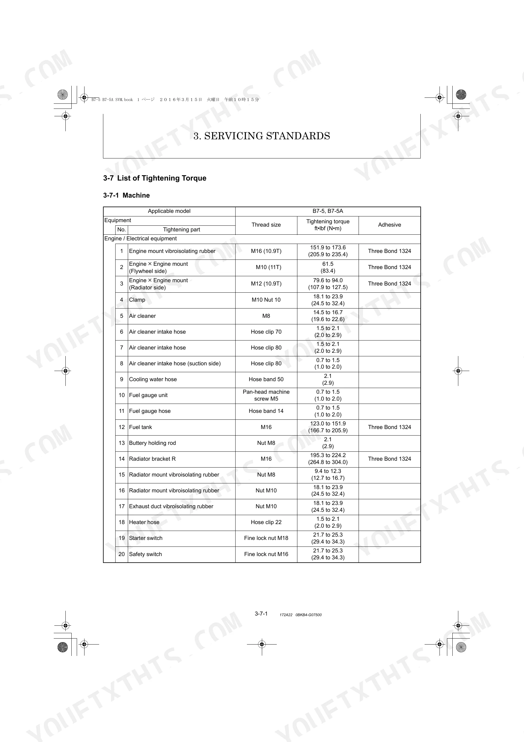
| Service Standards | 44-69 | Machine Performance, Engine, Undercarriage (Rubber Crawler Specifications, Steel Crawler Specifications, Common Specifications of Steel & Rubber Crawlers), Controls |
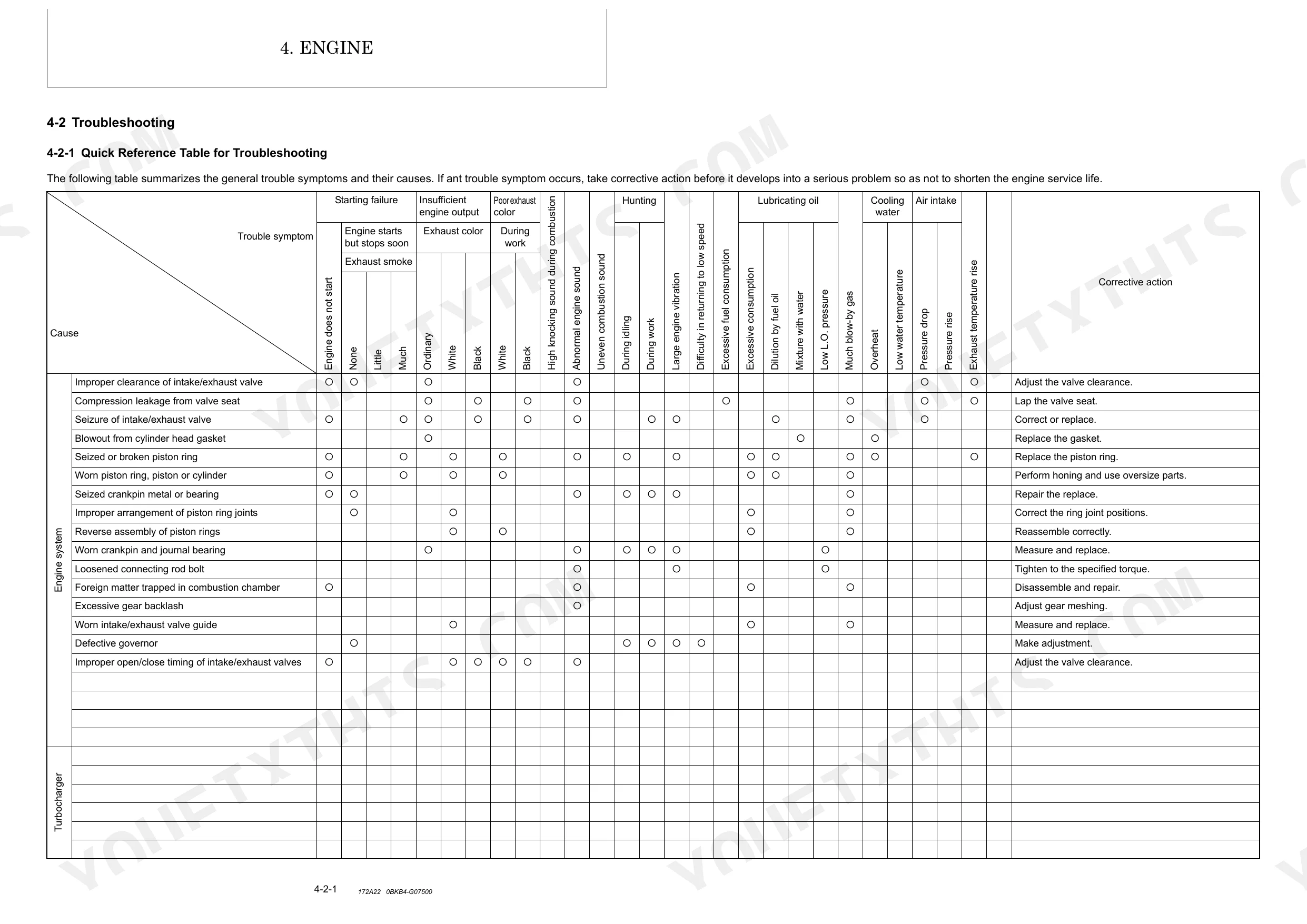
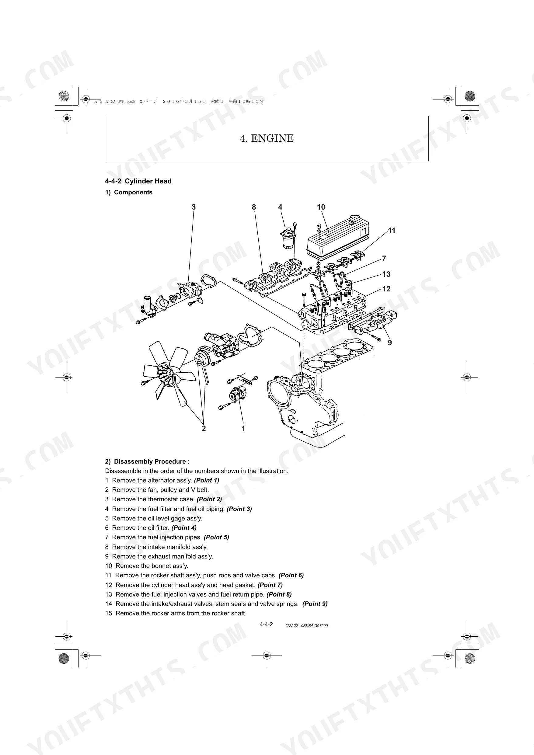
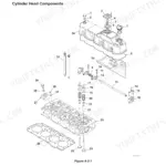
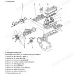
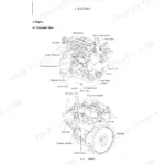
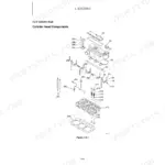
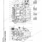
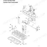
| Engine | 70-243 | B7-5 (General, Troubleshooting, Adjustment, Engine Body, Lubrication System, Cooling System, Fuel Injection Pump / Governor, Starting Motor, Alternator, Special Service Tools) |
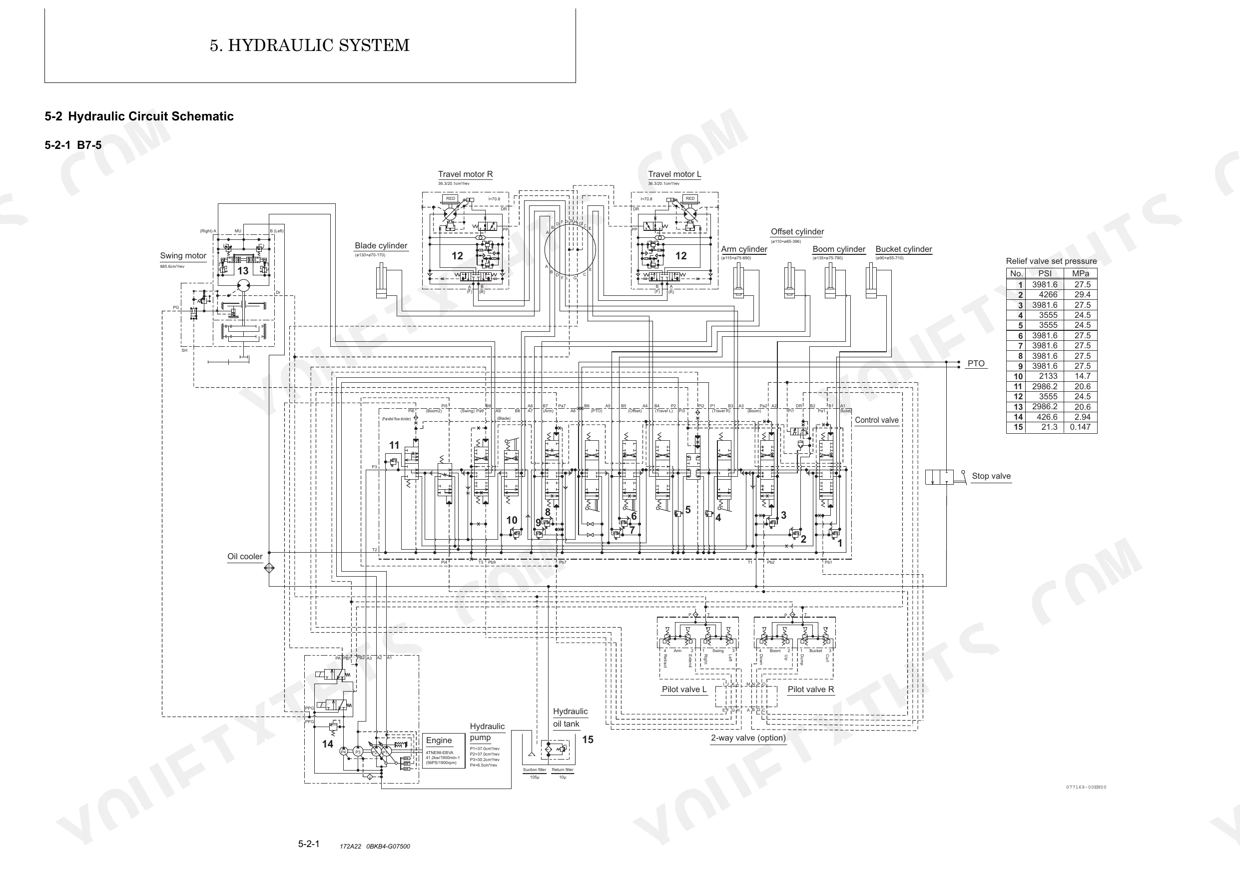
| Hydraulic System | 244-281 | Outline (Control Valve Operation, Additional Operation of Control Valve), Hydraulic Circuit Schematic (B7-5, B7-5A) |
| Hydraulic Equipment | 282-489 | Removal and Reinstallation of Hydraulic Pump, Removal and Reinstallation of Control Valve, Removal and Reinstallation of Swing Motor, Removal and Reinstallation of Swivel Joint |
| Adjustment and Repair | 490-595 | Electric Equipment of the Machine (Parts Layout of Electrical Equipment, Monitor and Alarm Systems, Wiring Diagram, Circuit Description of Engine Start, Stop and Battery Charging, Removal and Reinstallation of Engine, Removal and Reassembly of Starter Motor) |
| Periodic Inspection and Servicing | 596-599 | 8-1 List of Periodic Inspection and Servicing |
| Fuel, Lube Oil and Grease Recommended | 600-603 | Fuel, Engine Oil, Hydraulic Oil, Cooling Water, Grease, Antifreeze |
| Troubleshooting | 604-641 | 10-1 Non-Breakdowns, 10-2 Troubleshooting |
| Reference Data | 642-645 | 11-1 Specifications for Attachment, 11-2 Standard Bucket Specifications |
Quick Reference Specifications
| Specification | Value | Page |
|---|---|---|
| Swing bearing bolt tightening torque | 195.3 to 224.2 ft•lbf (264.8 to 304.0 N•m) | p. 64 |
| Travel motor to Track frame bolt tightening torque | 123.0 to 151.9 ft•lbf (166.7 to 205.9 N•m) | p. 64 |
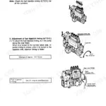
| Air Release Procedure | 1. Air release of variable displacement piston pumps: 1) Put specified quantity of hydraulic oil into tank. 2) Keep oil supply cap removed. 3) Install air bleeder hose onto bleeder valve and loosen half a turn. 4) Check all air released. 5) Tighten bleeder valve. 2. Air release of each hydraulic component: Run engine at medium speed and activate circuits for 10 to 15 minutes. 3. Air release of hydraulic cylinders: 1) Set engine speed at low idling. 2) Extend and retract cylinder up to 2 to 4 in. (50 to 100 mm) from each stroke end slowly 4 or 5 times. 3) Then, fully extend and retract the cylinder 3 or 4 times. | p. 22 |
| Piston assembly - Clearance (Standard dimension) | 0.002 in. (0.04 mm) | p. 48 |
| Pilot valve handle mounting nut tightening torque (Loctite 262) | 22 ft lbf (30 N·m) | p. 373 |
| Return filter - Filtration accuracy | 10 μ | p. 29 |
| Overall length (Transportation position) | 227.56 in. | p. 26 |
| Minimum ground clearance | 14.96 in. | p. 26 |
| Maximum digging force Bucket | 12326.0 lbs | p. 27 |
| Hydraulic oil tank Tank capacity | 26.4 Gals | p. 29 |
| Return filter Filtration accuracy | 10 μ | p. 29 |
| Engine Rated output | 55.2 HP | p. 31 |
Yanmar B7-5, B7-5A Common Problems This Manual Covers
Yanmar B7-5 excavator one track dead or significantly weaker than opposite side during travel
Check travel device troubleshooting steps on page 604. Inspect hydraulic lines to both travel motors for visible damage or restriction, then compare case drain flow between sides; higher drain on one motor confirms internal wear or failure. When replacing, torque travel motor mounting bolts to 123.0 to 151.9 ft•lbf (166.7 to 205.9 N•m) per page 64.
Manual Section: Troubleshooting p. 604Hydraulic cooling blower motor not running, engine temperature gauge rising during normal operation
Verify hydraulic oil level first; the tank capacity is 26.4 gallons and low fluid can starve the blower motor circuit. Check the hydraulic circuit schematic on page 244 to trace the motor supply and return lines. Inspect the motor for shaft seizure or internal leakage, and measure inlet pressure before replacing the unit.
Manual Section: Hydraulic System p. 244Boom and arm cylinders jerky or spongy immediately after hydraulic pump removal and reinstallation
Bleed air from the piston pump before running under load. Fill the tank to 26.4 gallons, install the bleeder hose on the pump bleeder valve, and crack it open half a turn until air clears. Then run the engine at medium speed and cycle all circuits for 10 to 15 minutes per the air release procedure on page 22.
Manual Section: General Cautions for Maintenance Work p. 22Engine turns over slowly or cranks but won't fire in cold morning conditions
Check battery terminals for corrosion and verify the alternator is charging; start with the battery charge alarm steps on page 604. Inspect glow plugs and confirm fuel grade suits ambient temperature. If the engine cranks but won't fire, measure compression; minimum spec is 493 PSI, with your model's exact limit on page 31 (B7-5) or page 34 (B7-5A).
Manual Section: EngineBoom raise or arm extend movement sluggish, cycle times exceed specified performance values
Test boom raise time against the 4.0-second standard and arm extend against 2.6 seconds; both specs are on page 44. If either runs slow, check hydraulic oil level against the 26.4-gallon tank capacity and inspect the return filter for a clogged 10-micron element. Trace the circuit on page 244 before disassembling any control valve.
Manual Section: Service Standards p. 44Frequently Asked Questions
How to relearn or recalibrate hydraulics on a Yanmar B7-5A?
To recalibrate hydraulics, perform pressure adjustments for the relief valves. For circuit relief valves, extend each cylinder to its stroke end, hold the lever, and read the gauge. If the pressure is lower than the system relief valve, increase it by turning the adjuster screw clockwise until the specified pressure is obtained, then lock the adjust screw. Additionally, after installing hydraulic components, release air from the hydraulic system by running the engine at medium speed and activating circuits for 10 to 15 minutes, or for cylinders, extend and retract them slowly 4 to 5 times up to 2 to 4 inches (50 to 100 mm) from each stroke end, then fully extend and retract 3 or 4 times. p. 277
Yanmar B7-5 torque specs for swing bearing bolts
For the Yanmar B7-5, the tightening torque for swing bearing bolts (M16) is 195.3 to 224.2 ft·lbf (264.8 to 304.0 N·m). Loctite 262 or its equivalent should be applied as an adhesive for these bolts. p. 64
What are the replacement specifications for hydraulic motor?
For the hydraulic motor, parts showing striking damage should be replaced. Specific components like the balance plate (7), cam plate (20), piston S/A (18), cylinder bores (16), and teflon ring (13) have wear limits and damage criteria that necessitate repair or replacement of the part or the entire motor assembly. For instance, if cylinder bores (16) show wear, the entire motor should be replaced. p. 429
What are the replacement specifications for controller?
For the control valve, all parts showing striking damage should be replaced. Components like the load check valve, springs, spools, relief valves, anti-void valves, O-rings, seals, and wipers have specific inspection criteria. If a load check valve's seat surface is dented, it should be repaired by lapping. If a spool shows wear or pitting, it should be repaired by lapping. If a relief valve or anti-void valve does not operate properly, it must be replaced as a valve assembly. O-rings, seals, and wipers should always be replaced with new ones when reassembled. p. 361
How will I receive this Service Manual?
Immediate download of the complete 645-page searchable Service Manual. Access it on any device, from a laptop at your desk to a phone in the field.
Are there any print restrictions on this manual?
Yes, print as many copies as you want, and there are no restrictions. Many mechanics print the section they need and bring it to the shop floor.
Can I find wiring schematics in this Yanmar B7-5, B7-5A manual?
Yes, full electrical schematics are included with wire colors, connector locations, and circuit descriptions.


Reviews
There are no reviews yet.