


Part of the Case Repair Manuals.
All 195 pages of this Case Compact Loader Service Manual (OEM #GSS-1476-2) are built around one machine family: the 4120, 4125, 4130, 4135, 4136, 4140, 4150, and 4155. Inside you get model-specific hydraulic and hydrostatic schematics, full wiring diagrams for every variant from the 4120 through the 4155, and troubleshooting charts that walk through pump failures and hydrostatic drive faults without guesswork. A complete run of exploded views spans the pump drive housing, wheel drive cases, and ROPS loader assembly, backed by torque tables covering standard hardware and hydraulic tube fittings. Torque the cylinder anchor nuts to 1315-1355 N·m (970-1000 ft. lbs.) and seat the 1-1/8-inch rod seal with tool 8101-533: those are your actual factory numbers, not somebody's best guess on a forum. No more chasing specs that may be wrong. Download the PDF, jump to any bookmarked section, search by keyword, and get your machine back in the field.
What's Inside This Case 4120–4155 Manual
| System | Pages | Key Topics |
|---|---|---|
| Safe Work Rules | 5-6 | Work Safely – Follow These Rules, To Prevent Injury, Always Use Safety Stands, Always Wear Safety Glasses, Keep Work Area Organized and Clean, Reinstall Safety Devices |
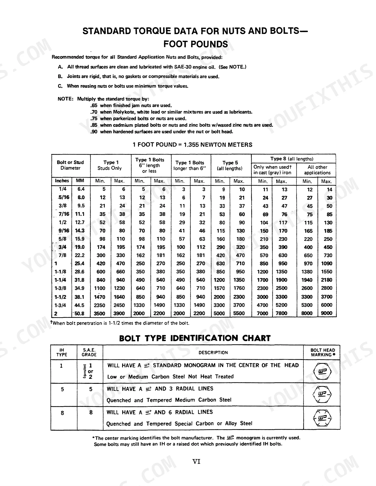
| Standard Torque Data for Nuts and Bolts | 7-8 | Standard Torque Data for All Standard Application Nuts and Bolts, Provided, Foot Pound = 1.355 Newton Meters, Bolt Type Identification Chart, Newton Meter = 0.738 Foot Pound |
| Metric Conversion Tables | 9-10 | Conversion Table - Inches to Millimeters, Inch = 25.4 Millimeters, Example to Convert 2.4635 Inches to Millimeters, Conversion Table - Millimeters to Inches, Mm = .03937008 Inches |
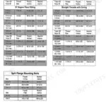
| Standard Torque Data for Hydraulic Tubes and Fittings | 11-13 | Tube Nuts for 37° Flared Fittings, O-Ring Boss Plugs, Adjustable Fitting Lock Nuts, Swivel Jic 37° Seats, Instructions for the Adjustable Standard Thread Tube Fittings |
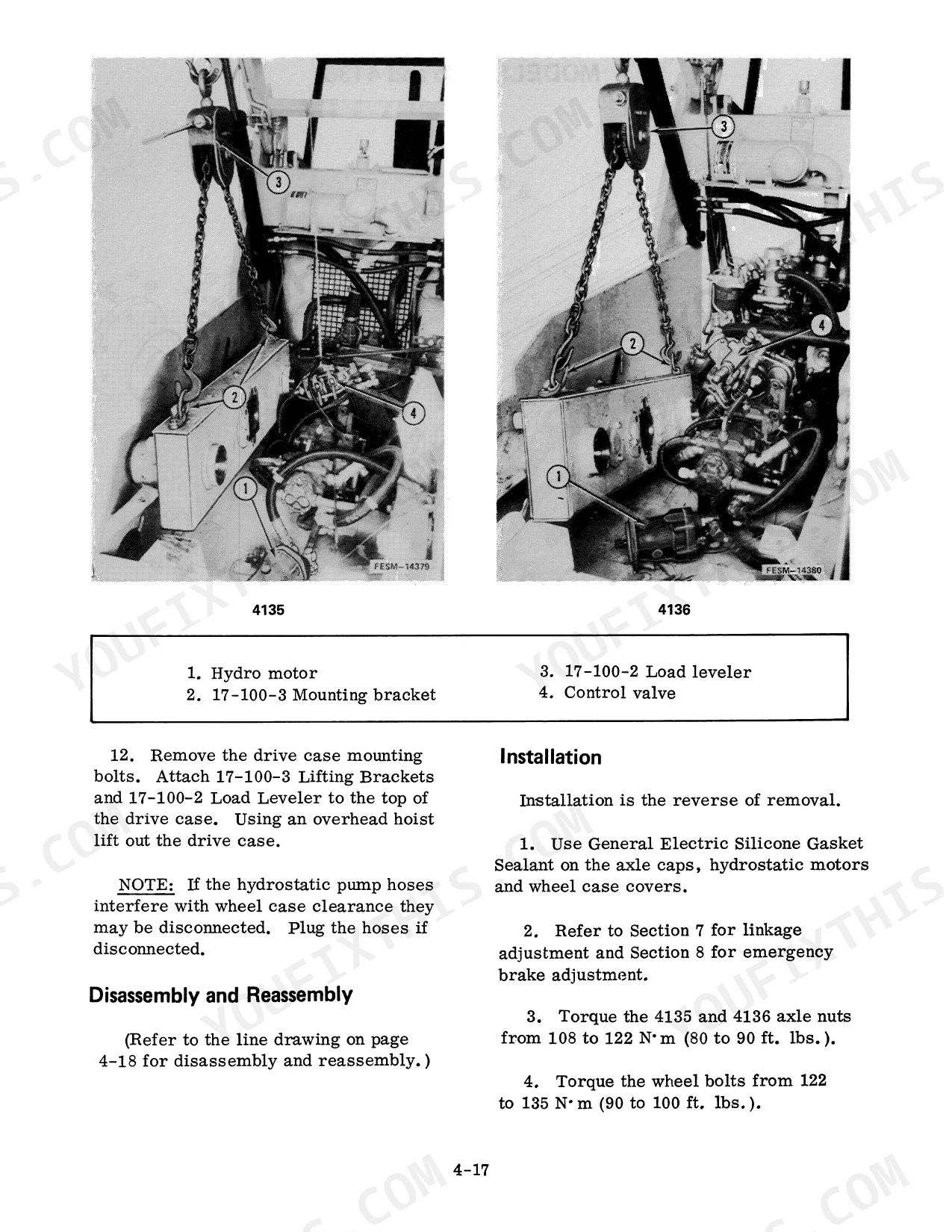
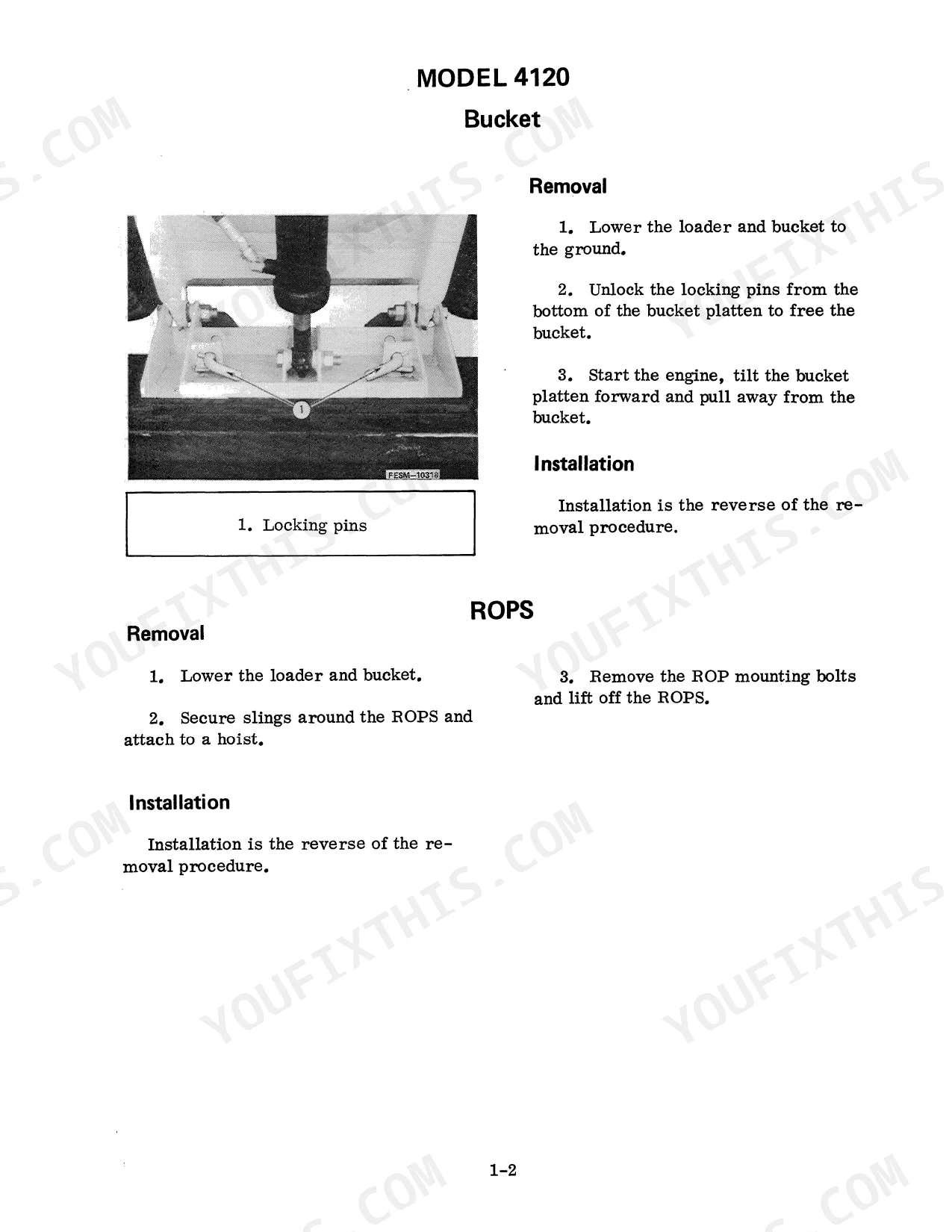
| ROPS Protective Frame - Loader | 14-19 | Model 4120 (Bucket, ROPS, Loader), Models 4130, 4135, 4136, 4150 and 4155 (Bucket, Models 4135, 4140 |
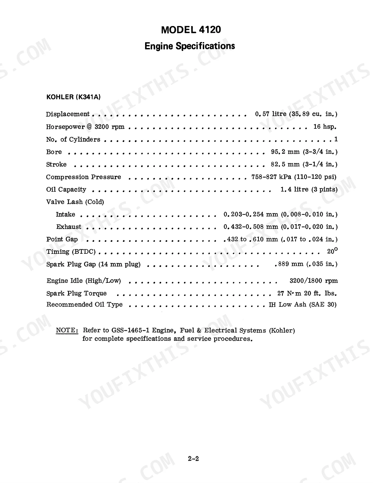
| Engine | 20-51 | Model 4120 (Engine Specifications), Model 4125 (Engine Specifications, Fuel Tank), Models 4130 and 4135 (Engine Specifications), Model 4136 (Engine Specifications) |
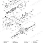
| Pump Drive Housing | 52-63 | Model 4130, Models 4140, 4150 and 4155, Model 4150, Model 4130 Pump Drive Housing, Removal, Disassembly, Inspection |
| Wheel Drive Case | 64-81 | Model 4125, Front Wheel Case, Rear Wheel Case, Models 4120, 4130, 4140, 4150 and 4155, Wheel Case - Models 4135 and 4136 |
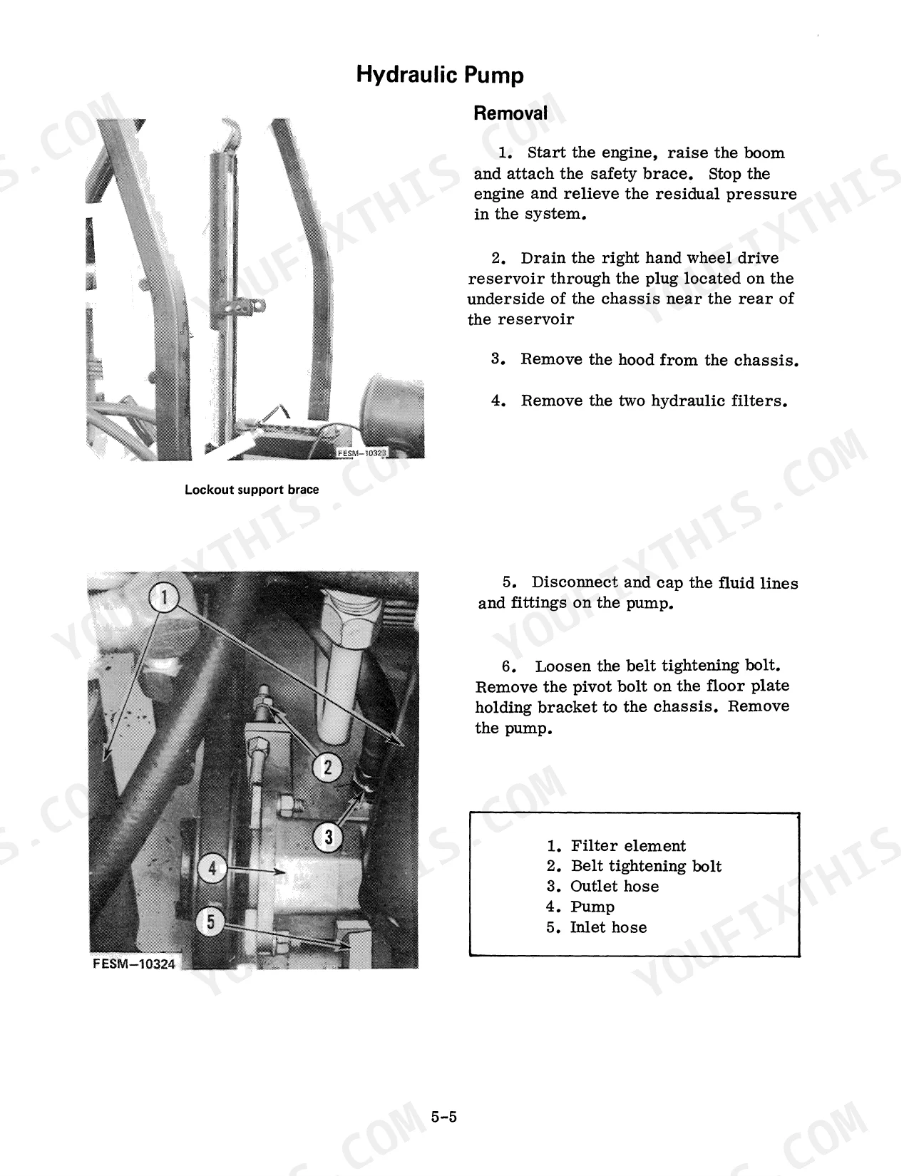
| Hydraulic System | 82-111 | Model 4120 (Specifications, Relief Valve Pressure Test, Relief Valve Adjustment, Hydraulic Pump Test, Hydraulic Pump, Control Valve, Troubleshooting) |
| Hydrostatic Drive | 112-161 | Model 4120 (Hydro-Transmission, Belt Adjustment, Troubleshooting), Model 4125 (Hydro-Transmission, Belt Adjustment) |
| Linkage and Seat Adjustment | 162-169 | Model 4120 and 4125 (Drive Linkage Adjustments), Models 4130, 4140 and 4150 (Drive Linkage Adjustment), Models 4125, 4130, 4140 and 4150 (Seat Lock Adjustment), Models 4135 |
| Brakes | 170-177 | Park Brake, Model 4125, S/N 131 and Below, S/N 132 and Above, Models 4135 and 4136, Model 4140, Model 4150 |
| Electrical System | 178-195 | Model 4120, Model 4125, Model 4130, Model 4135, Model 4136 (Alternator Drive Belt Replacement), Model 4140, Model 4150, Model 4155 |
Quick Reference Specifications
| Specification | Value | Page |
|---|---|---|
| All Models | ||
| Cylinder anchor nuts torque | 1315-1355 N·m (970-1000 ft. lbs.) | p. 106 |
| Rod seal installing tool for 1-1/8 inch rod seals | 8101-533 | p. 107 |
| MODEL 4155 | ||
| Tie bolts torque (4155 Control Valve) | 25 to 40 ft. lbs. | p. 101 |
| Spool cap mounting screws torque (4155 Control Valve) | 10 to 13 ft. lbs. | p. 101 |
| Model 4136 | ||
| Model 4136 Engine Oil Capacity | 3.785 litres (4 quarts) | p. 32 |
| Model 4140 (Diesel) | ||
| Model 4140 (Diesel) Engine Torque (max, at 2000 rpm) | 104 Nm (77 ft. lbs.) | p. 37 |
| Model 4140 (Gasoline) | ||
| Model 4140 (Gasoline) Engine Torque (max, at 1500 rpm) | 77 ft. lbs. | p. 37 |
Case 4120–4155 Common Problems This Manual Covers
Engine won't start or turns over slowly after fluid check
Inspect battery terminals for corrosion and clean to bare metal; a voltage drop above 0.5V across a terminal will kill the starter circuit. Test the starter relay by jumping it directly — if the engine cranks, replace the relay. Check fuel for water contamination: drain the primary filter bowl and look for separation. Verify injector lines show no air bubbles when cracking the fittings during cranking. Electrical system wiring diagrams begin at page 178.
Manual Section: Electrical System p. 178Hydrostatic drive on 4150 slows to a stop under load but turns freely unloaded
Measure case drain flow at the motor drain port — excessive flow confirms internal motor bypass and the motor needs rebuild or replacement. Verify charge pressure is within spec before condemning the motor; low charge pressure mimics the same symptom. Check for a clogged suction strainer and inspect the pump for shaft seal leakage. Full diagnostic steps for this condition are on pages 180-181.
Manual Section: Hydrostatic Drive Troubleshooting (Model 4150) p. 180Hydraulic oil foaming and sluggish loader response on 4130 through 4155 models
Drain a sample and check for milky or frothy oil — water ingestion causes foaming. Inspect all suction-side fittings and the pump inlet seal for air leaks; even a pinhole pulls air under suction. Verify oil level is correct and the return line terminates below fluid surface in the reservoir. Refer to the troubleshooting index on page 139 for the full foaming diagnostic specific to models 4130, 4135, 4136, 4140, 4150, and 4155.
Manual Section: Hydraulic System Troubleshooting (Models 4130, 4135, 4136, 4140, 4150, 4155) p. 139Model 4155 control valve leaks internally after reassembly
Verify tie bolts have Loctite thread sealant applied before installation and torque them to 25-40 ft. lbs. (page 101). Torque spool cap mounting screws to 10-13 ft. lbs. — under-torqued caps are the most common post-rebuild leak source. Inspect spool bores for scoring before closing the valve; a scratched bore will leak past new seals regardless of torque.
Manual Section: Hydraulic System p. 101Frequently Asked Questions
How do you fix hydraulic system overheats after 30 minutes of continuous loader operation?
Check the hydraulic return filter first — a clogged element is the leading cause on these machines. Verify the cooling fan spins freely and the relay closes under load. Inspect hydraulic fluid level and condition; contaminated or aerated oil runs hot fast. Consult the troubleshooting chart on page 122 for the full diagnostic sequence specific to the 4120 hydraulic system. p. 122
How do you fix
Remove the boom lift cylinder and inspect rod seals for wear or scoring. Use installing tool 8101-533 for 1-1/8 inch rod seals or 8101-534 for 1-1/2 inch rod seals when pressing in new seals (page 107). Torque cylinder anchor nuts to 1315-1355 N·m (970-1000 ft. lbs.) on reassembly. Also bench-test the main control valve spool for internal bypass — a sticky or worn spool lets pressure bleed down under load. p. 107
What format is this Case 4120, 4125, 4130, 4135, 4136, 4140, 4150, 4155, MODEL?
Immediate download of the complete 195-page searchable Service Manual (37 MB). Access it on any device, from a laptop at your desk to a phone in the field.
Are there any print restrictions on this Case 4120, 4125, 4130, 4135, 4136?
Yes. The PDF has no DRM restrictions, so print any page or section you need for your shop. Works with any standard printer.
Can I find wiring schematics in this Case 4120, 4125, 4130, 4135, 4136, 4140?
Complete wiring diagrams are included, covering all electrical circuits, harness routing, and connector pinouts for the Case 4120, 4125, 4130, 4135, 4136, 4140, 4150, 4155, MODEL 4130, MODEL 4135, MODEL 4136, MODEL 4140, MODEL 4150, MODEL 4155, 4120 Loader, 4125 Loader.


Reviews
There are no reviews yet.