





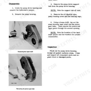
Part of the Case Repair Manuals.
Need factory-level guidance for your Case 150-190, T90, 2310, 2510, or 2712 compact tractor? This 202-page service manual (OEM #9-77981) covers every major system from engine block to transmission. You get wiring diagrams for the 150-190 and T90, hydraulic schematics covering the pump, control valve, and orbital motor, and a full troubleshooting section, with engine specs broken out separately for the 2310/2510-HH100 and 2712-HH120 variants. Open to the fuel system chapter for carburetor and fuel pump procedures, or jump straight to the transmission section: removal, disassembly, inspection, assembly, reinstallation. If your hydraulic lift is dragging, check control valve leakage at the 1/2 GPM limit, then back the relief valve off a half turn to drop pressure 100 PSI. Your machine's down. Bookmarked by section and keyword-searchable on any device: grab your tablet, walk to the tractor, and get back to work.
Complete the set for your 150-190, T90, 2310…
- Operator Manual: Case 2510 Cruz-Crane Service and Operator Manual
What's Inside This Case 150-190, T90, 2310, 2510, 2712 Manual
| System | Pages | Key Topics |
|---|---|---|
| Specifications | 9-32 | Engine, Electrical, Wiring Diagram, 150-190, T90 |
| Engines | 33-126 | Assemblies Contained in the Engine Block, 2310 and 2510-HH100, 2712-HH120, Electrical, Wiring Diagram, Carburetor |
| Fuel System | 127-140 | Carburetor, Fuel Pumps |
| Hydraulic System | 141-168 | How It Works, Hydraulic Pump, Control Valve, Orbital Motor |
| Steering | 169-186 | Steering System, Front Axles |
| Transmission | 187-202 | Introduction, Removal, Disassembly, Inspection, Assembly, Installation |
Quick Reference Specifications
| Specification | Value | Page |
|---|---|---|
| All Models | ||
| Control Valve Leakage Limit | more than 1/2 GPM | p. 152 |
| Relief Valve Pressure Adjustment (Decrease) | one half turn (only) for 100 PSI reduction, or 200 PSI per shim | p. 153 |
| Starter-Generator Drive Belt Deflection | 1/4" | p. 20 |
| 150-190, T90 | ||
| Carburetor High Speed Adjustment (Kohler engines) | Approximately two turns | p. 133 |
| Carburetor Idle Mixture Adjustment (Kohler engines) | approximately 1-1/4 turns from the closed position | p. 133 |
| K241 engine | ||
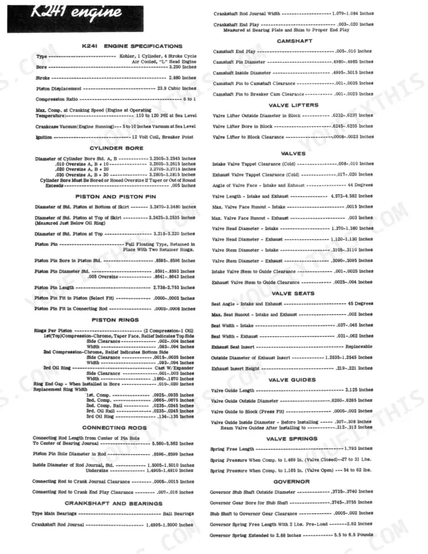
| K241 Piston Displacement | 23.9 Cubic Inches | p. 11 |
| K301 engine | ||
| K301 Piston Displacement | 29.07 Cubic Inches | p. 12 |
| K241, K301 engines | ||
| Cylinder Head Bolts Torque (K241/K301) | 33 Ft. Lbs. | p. 13 |
| Spark Plug Torque (K241/K301) | 27 Ft. Lbs. | p. 13 |
Case 150-190, T90, 2310, 2510, 2712 Common Problems This Manual Covers
Case compact tractor engine stalls during mowing or tilling despite recent fuel system maintenance
Check the carburetor for varnish buildup and debris in the main jet. Disassemble per page 127, inspect the needle valve and float for wear, then reassemble. For 150-190 and T90 models, set the high speed screw approximately two turns out from seated, then adjust idle mixture counter-clockwise approximately 1-1/4 turns from closed position. Test under load before returning to service.
Manual Section: Fuel System p. 127Hydraulic lift fails to raise implements or lowers unevenly under load
Test system pressure at the pump outlet first; then check control valve leakage. If leakage exceeds 1/2 GPM, inspect the relief valve setting before condemning the control valve body. Adjust the relief valve by turning the adjusting screw no more than one half turn at a time, each half turn changes pressure approximately 100 PSI; alternatively remove shims, each shim removes approximately 200 PSI. See the full pressure and flow check procedure starting on page 152.
Manual Section: Hydraulic System p. 152Engine overheats after 20-30 minutes of operation under normal working conditions
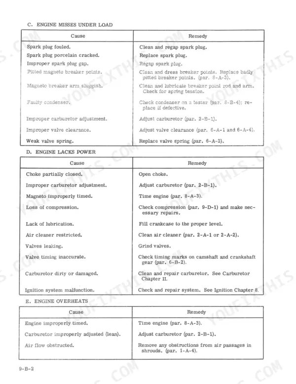
Inspect the cooling fins on the cylinder head for packed debris and clean with compressed air. Check the starter-generator drive belt: depress it between pulleys with finger pressure, it should deflect exactly 1/4". A loose belt slips and reduces cooling airflow. Verify the engine oil level and condition; low oil accelerates heat buildup. If overheating continues, check coolant passages and the shroud for missing or damaged sections that short-circuit airflow.
Manual Section: Engines p. 20Engine turns over slowly or won't start in cold weather conditions
Inspect the battery terminals for corrosion and check specific gravity. Verify the starter-generator belt deflects 1/4" under finger pressure between pulleys — a loose belt causes slow cranking and low charging voltage. Check ignition contact points, timing, and spark plug condition per the electrical diagnostics starting on page 16. Torque spark plugs to 27 Ft. Lbs. on K241 and K301 engines after any plug service.
Manual Section: Specifications p. 16Electrical system shows erratic charging or battery drains overnight after one season of use
Inspect the starter-generator belt first: correct deflection is 1/4" under finger pressure between pulleys; a worn or loose belt causes undercharging. Check the voltage regulator output and verify all ground connections at the frame and battery terminals are clean and tight. Trace the wiring against the diagram on page 28 to locate any chafed insulation or broken leads. Replace the regulator if charging voltage falls outside spec after belt and connection corrections.
Manual Section: Specifications p. 28Transmission shifts hard or jumps out of gear under load during normal field operation
Drain the transmission and inspect the oil for metal particles — any shiny debris means internal gear or shift fork wear. Remove the transmission per the procedure starting on page 187, then disassemble and inspect shift fork engagement grooves and detent balls for wear. Check all bearing races for pitting. Reassemble with fresh oil to the correct fill level per the specifications section before reinstalling.
Manual Section: Transmission p. 187Frequently Asked Questions
What exactly do I receive with this Case 150-190 Service Manual?
A 202-page Service Manual in searchable PDF format (36 MB), available the moment you complete checkout. View on computer, tablet, or phone, with no shipping wait.
Can I print just the pages I need from this Case 150-190 manual?
Yes, print as many copies as you want, and there are no restrictions. Many mechanics print the section they need and bring it to the shop floor.
Is there a wiring diagram in this Case 150-190 Service Manual?
Yes. You'll find full electrical schematics with wire routing diagrams, connector identification, and circuit descriptions.









Reviews
There are no reviews yet.