


Part of the Case Repair Manuals.
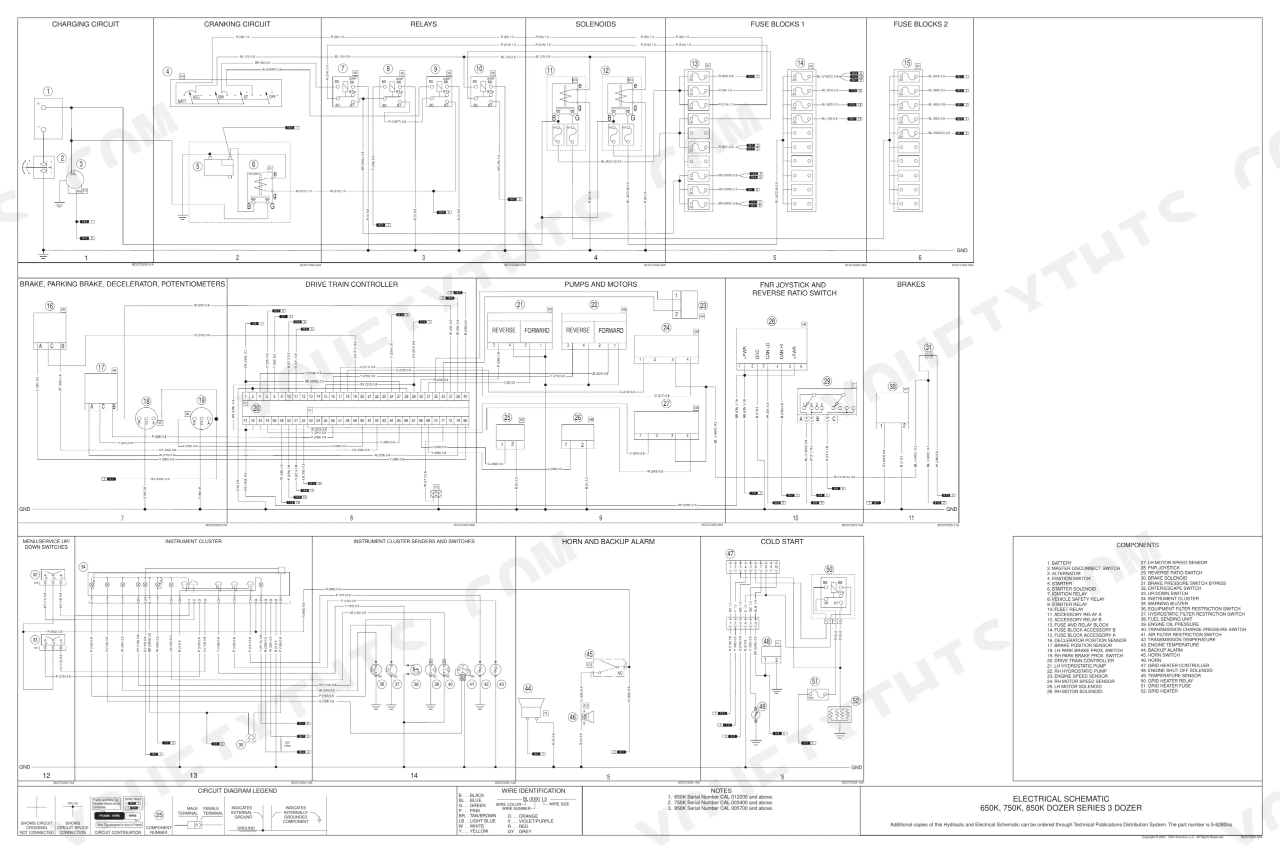
Need the factory repair data for your Case 850K Crawler Dozer? This 1,362-page repair manual (OEM #87364103 NA) covers the full 650K, 750K, and 850K family. Inside: complete electrical schematics for the battery, alternator, ignition switch, and Drive Train Controller, plus full hydraulic schematics covering the hydrostatic pump, brake solenoid valve assembly, and lift cylinder circuits. You also get a packed fault code library, connector pinouts for every control harness, torque tables, calibration data, and step-by-step procedures spanning the hydrostatic transmission, final drive, tracks, blade, and engine. Torque the hydraulic pump cover bolts to 66-80 Nm (49-59 lb ft) and set control valve spool travel to exactly 7.9 mm from neutral to pressure. Your dozer is down. Bookmarked and keyword-searchable; pull it up on any device and start the repair.
What's Inside This Case 650K, 750K & 850K Series 3 (Tier 2) Repair Manual
| System | Pages | Key Topics |
|---|---|---|
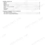
| Table of Content | 3-5 | - |
| Introduction | 6-19 | Basic Instructions, Hydraulic Contamination, Conversion Factors |
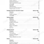
| Distribution Systems | 20-546 | Primary Hydraulic Power System, Secondary Hydraulic Power System, Electrical Power System, Lighting System, Fault Codes |
| Power Production | 547-656 | Engine, Fuel and Injection System, Air Intake System, Engine Coolant System, Lubrication System, Starting System |
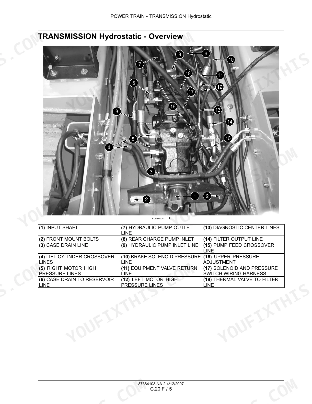
| Power Train | 657-726 | Power Coupling Fixed Coupling, Transmission Hydrostatic |
| Travelling | 727-974 | Service Brake Hydraulic, Parking Brake Hydraulic, Wheels and Tracks, Final Drive |
| Body and Structure | 975-1202 | User Controls and Seat, User Platform, Environment Control Heating System, Environment Control Air-Conditioning System, Environment Control Heating |
| Tool Positioning | 1203-1316 | Lifting, Tilting, Swinging |
| Working Arm | 1317-1326 | Single Arm Tool Attachment Lift |
| Tools and Couplers | 1327-1358 | Digging Non-Articulated Tools, Landscaping Dozer Blade, Hydraulic Schematic, Engine Repair Manual |
| Electrical Schematics | 1359-1361 | Battery, Alternator, Ignition Switch, Starter Solenoid, Fuse and Relay Block, Drive Train Controller |
| Hydraulic Schematicas | 1362 | Brake Solenoid Valve Assembly, Hydrostatic Pump Assembly, Diagnostic Panel Equipment Valve, Lift Cylinders, Tilt Cylinder, Oil Cooler Assembly |
Quick Reference Specifications
| Specification | Value | Page |
|---|---|---|
| Spool travel (Neutral to pressure - lift, tilt and auxiliary) | 7.9 mm (0.31 in) | p. 29 |
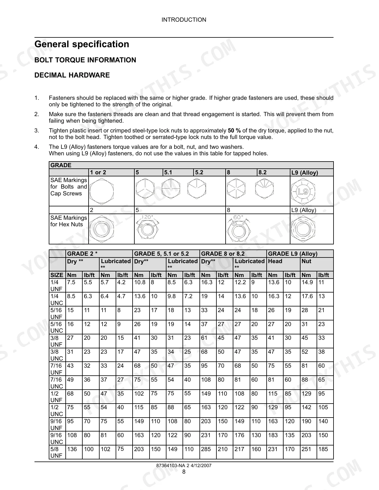
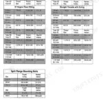
| Hydraulic pump cover bolts torque | 66 - 80 Nm (49 - 59 lb ft) | p. 31 |
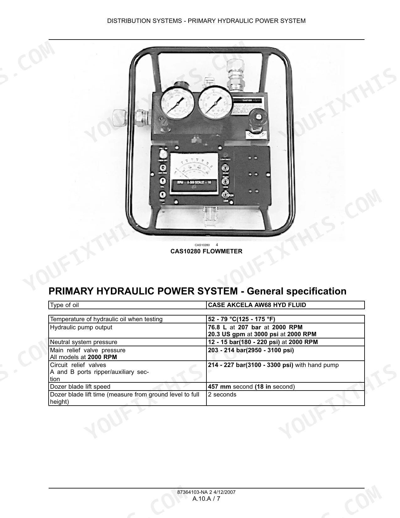
| Primary Hydraulic Pump Output (Temperature) | 52 - 79 °C | p. 28 |
| Alternator Rated output (65 Ampere) | 14 volts at 65 amps | p. 137 |
| Alternator Rated output (95 Ampere) | 14 volts at 95 amps | p. 137 |
| Fuel tank capacity | 189.3 L | p. 567 |
| Engine Coolant System Capacity (Without heater) | 18.9 L | p. 587 |
| Lubrication System Capacity (650K and 750K) | 13.6 L | p. 609 |
| Ripper Track shoes torque | 406 - 407 Nm | p. 1337 |
Case 650K, 750K & 850K Series 3 (Tier 2) Common Problems This Manual Covers
Case 850K Transmission Fault light illuminates at startup, display shows no forward/neutral/reverse indication
Check the error code reference first. Inspect all wiring harness connectors at the transmission control module for corrosion or backed-out pins. Verify the joystick CAN message signal and confirm no open circuit on the parking brake relay. Test left and right pump solenoid circuits for continuity. If module fault persists after connector cleaning, proceed to full transmission system testing starting at page 657.
Manual Section: Distribution SystemsHydraulic cylinder rod seals leaking, blade loses pressure mid-push and won't hold position
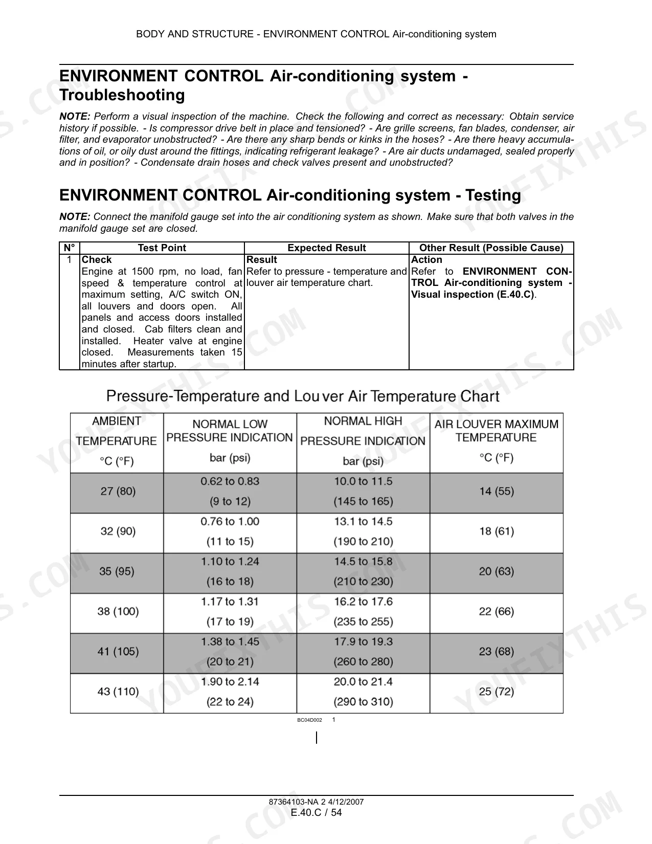
Inspect cylinder rod surfaces for scoring or pitting before replacing seals — a damaged rod destroys new seals immediately. Verify hydraulic oil temperature is within 52–79°C (125–175°F) during testing per specs on page 28. Drain and check fluid for contamination; particulate above acceptable limits accelerates seal wear. Reference the cylinder visual inspection procedure and leakage test in the Tool Positioning section, then the Ripper System visual inspection at page 1327 if rear cylinders are affected.
Manual Section: Tool Positioning p. 1203Control valve spools sticking after fluid change, blade and ripper movement erratic or unresponsive
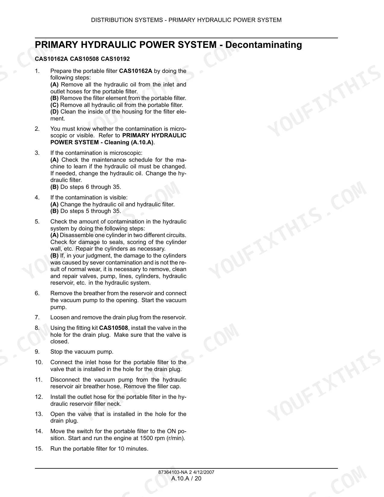
Verify spool travel from neutral to pressure is 7.9 mm (0.31 in) per the calibration spec on page 29 — a spool that won't reach full travel is partially seized. Cycle the blade through full lift, tilt, and auxiliary ranges 10–15 times with fresh fluid to flush debris from galleries. Inspect for contamination introduced during the fluid change; hydraulic contamination procedures start on page 6. If spool resistance remains after flushing, remove the control valve for bench inspection.
Manual Section: Distribution Systems p. 29Engine cranks slowly or won't start in cold weather, no cold start aid activation
Check battery voltage under load and verify the alternator output matches the rated 14 volts at 65 amps (or 95 amps on the higher-output unit) per page 137. Inspect the cold start aid circuit and start control relay per the engine starter electrical test in the Power Production section. Confirm fuel tank has at least partial fill — capacity is 189.3 L (50 US gal) per page 567. Test the starter solenoid for electrical resistance; replace if outside spec before condemning the starter motor.
Manual Section: Power Production p. 547Track tension incorrect after long operating hours, uneven wear on rollers and idler wheels
Measure and adjust steel track tension following the procedure in the Travelling section starting at page 727. Perform lower roller and idler wheel leakage tests as outlined in the track system testing . When reinstalling track shoes, torque fasteners to 406–407 Nm (300–330 lb ft) per page 1337. Inspect idler wheel seals during the same service interval — a leaking idler and a mis-tensioned track accelerate each other's wear.
Manual Section: Travelling p. 727Frequently Asked Questions
How to reset error codes on Case 650K/750K/850K dozer?
To reset error codes, first write down all fault codes, number of occurrences, and engine hours. Then, turn the ignition switch to the RUN position to power the drivetrain controller and clear all fault codes from the controller. This procedure is applicable for models 650K, 750K, and 850K. p. 359
What are the torque specs for engine bolts on Case 750K crawler?
For Case 750K crawlers, the engine mount bolts to the chassis should be torqued to 205 - 230 Nm (151 - 170 lb ft). The rear engine mount brackets to the bell housing require a torque of 118 - 133 Nm (87 - 98 lb ft).
How to reset maintenance timer on Case 850K dozer?
The manual indicates that the next service due lamp illuminates when service hours are more than 10 hours, and remains on when hours are zero or negative. However, it does not provide a specific procedure or reset button for the maintenance timer.
Where is the reset button for diagnostic codes on Case 650K?
The manual does not specify a physical 'reset button' for diagnostic codes on the Case 650K. Instead, it describes a procedure to clear fault codes by turning the ignition switch to the RUN position and clearing all fault codes from the drivetrain controller. p. 359
What do I get after purchasing this Case 650K & variants manual?
A 1362-page Repair Manual in searchable PDF format, available the moment you complete checkout. View on computer, tablet, or phone, with no shipping wait.
Are there any print restrictions on this manual?
The PDF is DRM-free. Print whatever sections you need to take out to the shop. Standard letter or A4 paper works.
Does this Case 650K & variants Repair Manual cover the hydraulic system?
Full hydraulic system diagrams are included, covering circuits, valve locations, and hydraulic component specs for the Case 650K & variants.


Reviews
There are no reviews yet.