

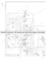
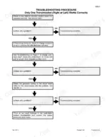

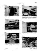

This 858-page Case 1840 Service Manual (OEM #8-11093) puts the full engine, hydrostatic drive, and hydraulics teardown for your Skid Steer in one place. Inside you'll find electrical schematics covering the starter, battery, and both alternator options, plus hydraulic circuit diagrams for the loader, auxiliary, and backhoe control valves, all backed by a rear-pocket foldout for quick reference at the bench. You get a dedicated troubleshooting section for the hydrostatic drive system alongside torque specs and fluid capacities up front. Set drive chain deflection to 10-13 mm total travel with roughly 6 mm clearance at the adjusting bolt, and swap the hydraulic filter every 5,000 hours or when that warning lamp lights up, hand-tight only, no strap wrench. No more chasing a chain-tension guess or a filter torque you half-remember. It's bookmarked by section, so you search the spec once and get back under the machine.
Complete the set for your 1840
- Parts Catalog: Case 1840 Skid Steer Loader Parts Catalog
What's Inside This Case 1840 Manual
| System | Pages | Key Topics |
|---|---|---|
| General | 4-21 | Section Index - General, Torque Specifications, Fluids and Lubricants |
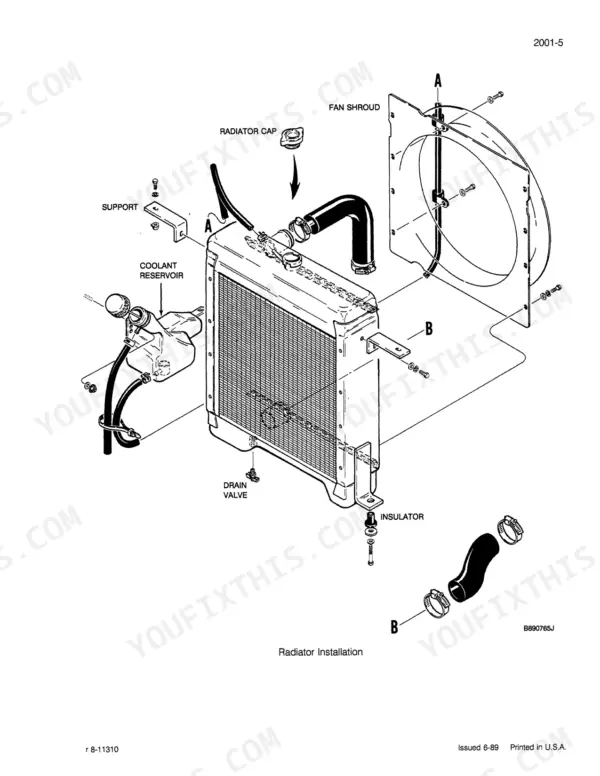
| Engines | 22-205 | Section Index - Engine, Engine and Radiator Removal and Installation, Specification Details, Cylinder Head and Valve Train, Cylinder Block, Crankshaft, Pistons, Rods |
| Fuel System | 206-245 | Section Index - Fuel System, Fuel System and Filters, Fuel Injectors, Cav Injection Pump1 |
| Electrical | 246-365 | Section Index - Electrical, Electrical How It Works, Removal and Installation of Electrical Components, Electrical Specifications and Troubleshooting and Schematics, Battery |
| Power Train | 366-501 | Section Index - Power Train, Hydrostatic How It Works, Removal and Installation of Power Train Components, Hydrostatic Drive System Troubleshooting, Controls, Piston Pump, Motor |
| Hydraulics | 502-727 | Section Index - Hydraulics, How It Works, Removal and Installation of Hydraulic Components, Hydraulic System Specifications and Troubleshooting and Schematics |
| Mounted Equipment | 728-855 | Section Index - Mounted Equipment, Control Linkages, Pedals and Levers How It Works, Pedals and Levers, Loader, ROPS Canopy, Seat, Seat Belts |
| Rear Pocket | - | Hydraulic and Electrical Schematic Foldout |
Quick Reference Specifications
| Specification | Value | Page |
|---|---|---|
| Hydraulic Filter (Type) | 6 micron spin on replaceable filter | p. 506 |
| Hydraulic Filter (Replacement Interval) | 5000 hours (or if warning lamp lights) | p. 541 |
| Cooling Fan Belt (Replacement Condition) | Replace if damaged | p. 15 |
| Cooling Fan Belt (Spring Tension at 35 Degree Angle) | 24 Nm | p. 194 |
| Engine Oil Capacity with filter change | 10.4 litres (11 U.S. quarts) | p. 13 |
| Engine Cooling System Capacity | 17 litres (18 U.S. quarts) | p. 13 |
| Hydraulic System Capacity | 39.7 litres (10.5 U.S. gallons) | p. 13 |
| Drive Chain Compartments Capacity (each) | 5.7 litres (6 U.S. quarts) | p. 13 |
Case 1840 Common Problems This Manual Covers
Case 1840 side chain box gaskets leaking hydraulic fluid onto the belly, staining and pooling
Drain the drive chain compartment (5.7 litres per side) before pulling the chain box covers. Inspect all 4 gaskets for hardening or tearing and replace the full set rather than one at a time; they're a common wear item at this age. Clean the mating surfaces of old sealant residue before fitting new gaskets, then refill each compartment to the 5.7 litre (6 U.S. quart) mark and recheck for seepage after a short run.
Manual Section: General: Maintenance Schedule p. 15Overtemperature warning lamp comes on with a heavily packed dirt and debris belly
Shut down and let the machine cool, then pull the belly guards and clear packed debris from around the cooling fan and radiator fins by hand before using compressed air or a wash; caked mud won't blow out first pass. This is an as-required interval item, not a fixed-hours one, so make it part of every service when operating in dusty or wet ground. Check the fan belt spring tension afterward; it should hold 24 Nm at a 35 degree angle, and a loose belt will let temps climb again fast.
Manual Section: General: Maintenance Schedule p. 15Hydraulic pressure low with slow or weak loader lift
Check the hydraulic filter first; it's a 6 micron spin-on unit and gets blamed for pressure drop more than the pump does. Replace it if the warning lamp is lit, if a component was recently swapped, or if it's logged near 5000 hours, whichever comes first. When installing, hand-tighten only 1/2 turn past O-ring contact; never use a strap wrench, over-torquing here is what causes the next leak. Verify tank level to the 39.7 litre (10.5 U.S. gallon) system capacity before chasing the pump.
Manual Section: Hydraulic System Troubleshooting - Loader Circuit ProblemsBattery won't hold charge or engine cranks slow in cold weather
Load-test the battery at its rated 685 amperes cold cranking capacity at 0°F; anything reading well under that spec should be replaced rather than trickle-charged and reinstalled. Confirm system voltage sits around 12 volts at rest with the key off. If the battery tests good but cranking is still weak, move to the alternator: rated output is 14 volts at 65 amperes on the A187873 unit, so a no-charge condition with the engine running points there next.
Manual Section: Electrical: Wiring Diagram p. 259Drive chains rattling or excessive slack felt through the pedals
Loosen the lock nuts and chain adjusting bolts until there's roughly 6 mm (1/4 inch) clearance between the adjusting bolt end and the axle housing, then move the axle housing away from the drive sprocket by tightening the bolts until the chains resist further movement. Turn each drive motor's adjusting bolt until total up-and-down deflection measures 10 to 13 mm (3/8 to 1/2 inch), matching both sides evenly so the machine doesn't pull.
Manual Section: Mounted Equipment p. 766Electrical fault in the control circuit with intermittent loss of function
Pull the suspect connector and check for corrosion or a loose crimp; a visual green or white residue on the pins is enough to condemn it. Test continuity across the harness rather than just wiggling wires, since a partial break often only opens under load or vibration. Confirm system voltage holds near 12 volts at the connector under load; a sagging reading there points to a bad ground or corroded splice further up the harness, not the component it feeds.
Manual Section: Electrical: Wiring Diagram p. 259Frequently Asked Questions
How do I adjust the hydraulic pressure on a Case 1840 skid steer loader?
To adjust the hydraulic pressure, you need to adjust the main relief valve. If the pressure is not correct, use pliers to remove the cap and adjust the main relief valve. The pressure must be 158 to 172 bar (2300 to 2500 psi) at full throttle for the loader main relief. p. 549
How do I troubleshoot tandem pump failure on a Case 1840 skid steer loader?
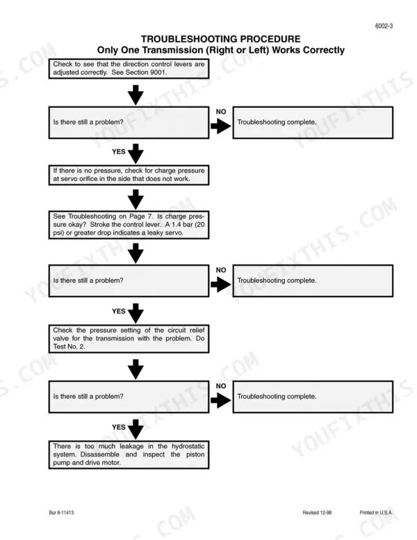
To troubleshoot tandem pump failure, if only one transmission works correctly or the machine does not have enough power, you should disassemble and inspect the piston pump and drive motor for worn or damaged parts. Refer to Section 6004 for detailed repair procedures. p. 395
Why does a Case 1840 skid steer loader not start below 15°F without glow plugs?
The Case 1840 skid steer loader uses an ether injection system for cold starting, not glow plugs. If the ambient temperature is above 35°F, the ether injection solenoid will be locked out by a temperature switch, indicating that ether is used for starting in cold conditions. p. 249
How do I check the charge pump on a Case 1840 skid steer loader?
To check the charge pump, connect a 0 to 345 bar (0 to 5000 psi) pressure gauge to the diagnostic coupler at the gear pump outlet test tee. The pressure must be 26 to 28 bar (390 to 415 psi) minimum at full throttle. p. 399
Is this Case 1840 manual a PDF I download?
Instant PDF download. You get the full 858-page searchable Service Manual immediately after payment. Open it on your laptop, tablet, or phone right in the shop.
Can I print specific sections of this Case 1840 Skid Steer manual?
No restrictions at all. Print individual pages, full chapters, or the entire manual. The PDF is completely unlocked.
Does this Case 1840 Skid Steer manual include wiring diagrams?
Yes, this Case 1840 Skid Steer Service Manual includes complete electrical wiring diagrams, wire routing, and connector pinouts.

Reviews
There are no reviews yet.