


Searching for an International 784 operator manual pdf that covers the full IH 84 Series? This 78-page OEM document (#1093396R2) puts all five variants under one cover: International 484, 584, 684, 784, and Hydro 84. Inside: a complete safety chapter covering startup, road transport, and upset recovery; step-by-step operating procedures for both gear-drive and hydrostatic models; and the full Selectamatic hydraulic section covering position control, draft control, auxiliary valves, and self-sealing couplings. You also get Preventive Maintenance with fluid change intervals, cooling system service, fuel filter steps, and storage prep, plus a factory specs table covering hydraulic output, tire loads, PTO data, and approximate weights. Set tie rod lock bolts to 8 kgm (60 lbft) after alignment, and confirm hydraulic pump output at 57 l/min before the machine goes back to work. The field won't wait. Download, bookmark to any section, and have factory answers right on your phone.
What's Inside This International 484-Hydro 84 Operator Manual
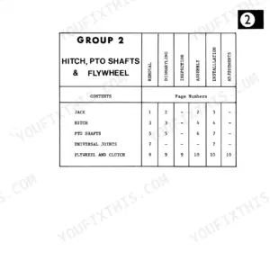
| System | Pages | Key Topics |
|---|---|---|
| Introduction | 11 | Terms of Location |
| Work Safety - Follow These Rules | 12-14 | Before Starting, During Operation, Transporting, After Operating, Dismounting, After an Upset |
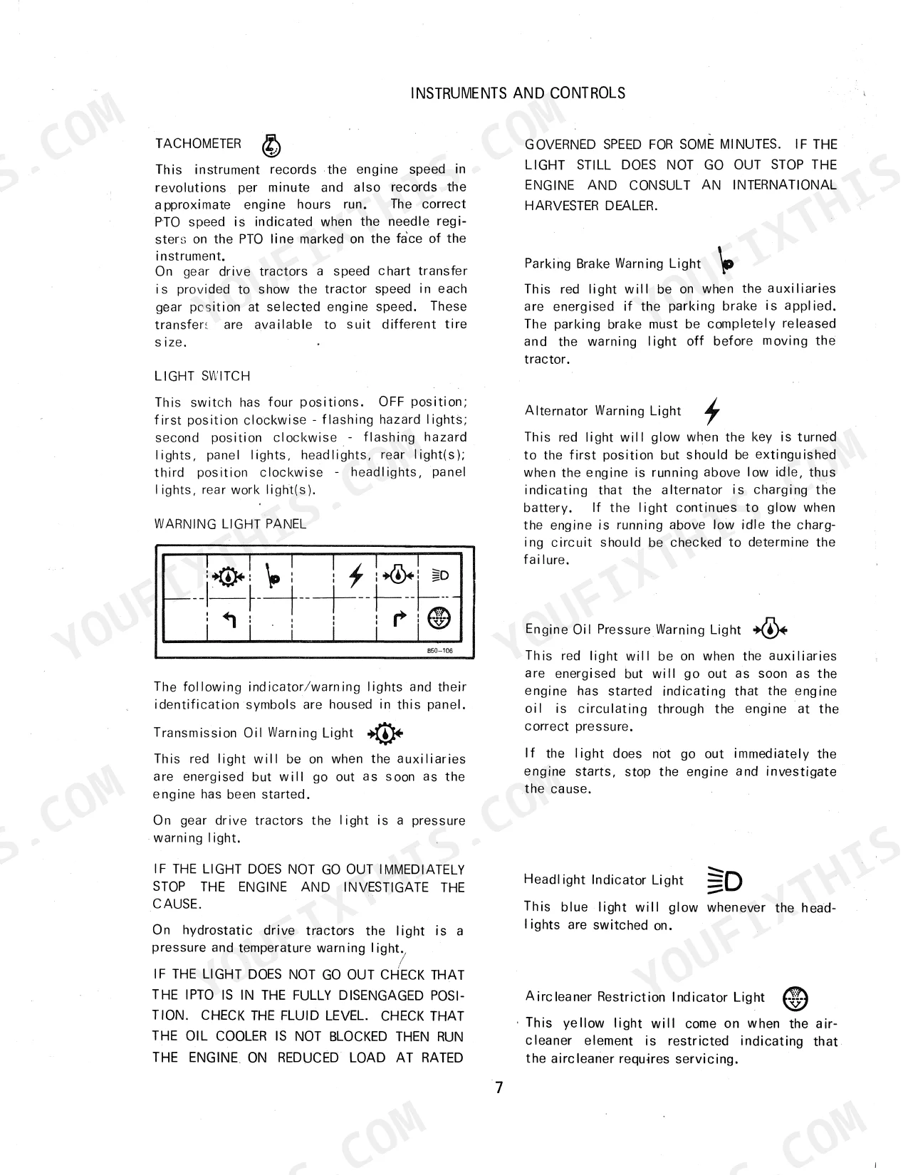
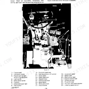
| Instruments and Controls | 15-20 | Tachometer, Warning Light Panel, Brake Pedals, Differential Lock Pedal, Position Control Lever, Independent PTO Lever |
| Before Operating the Tractor | 21 | Tractor Break-In Procedure |
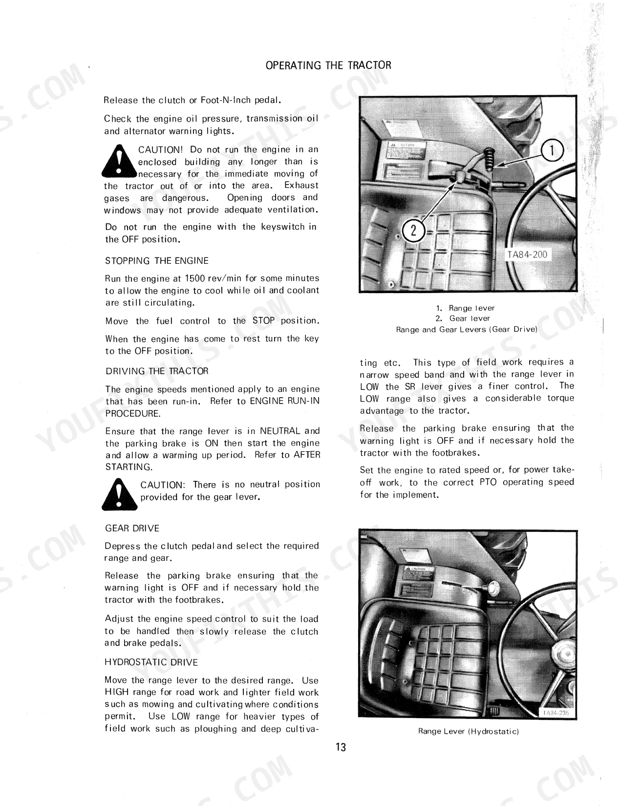
| Operating the Tractor | 22-28 | Starting the Engine, After Starting, Stopping the Engine, Driving the Tractor, Driving Hydrostatic Tractors, After Transporting or Servicing, Steering the Tractor |
| Hydraulic System | 29-32 | Position Control Lever, Adjustable Stop, Drop Response, Draft Control Lever, Raise Response Lever, Auxiliary Valves, Self Sealing Couplings, Thermal Expansion Pressure |
| Three Point Linkage | 33-35 | Lift Links, Lower Links |
| Wheels and Tires | 36-41 | Front Wheels, Tread Widths, Row Crop Tractors, Tire Pressures and Ballasting, Rear Wheel Weights, Rear Tire Loads and Inflation Pressures, Front End Weights |
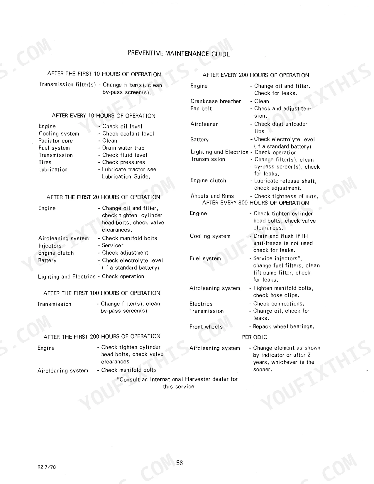
| Preventive Maintenance | 42-43 | Cooling System, Rust Prevention, Adding Coolant to the System, Draining the System, Flushing the System, Filling the System, Cleaning the Radiator and Oil Cooler Cores |
| Aircleaning System | 44-45 | Servicing the Aircleaner |
| Engine Servicing | 46 | Engine Oil, Checking the Crankcase Oil Level, Changing the Crankcase Oil, Changing the Filter, Crankcase Breather |
| Fuel System | 47-49 | Diesel Fuel Storage, Tractor Fuel System, Injection Pump, Fuel Tank, Fuel Filters, Venting the System, Changing the Ether Start Container, Injectors |
| Engine Clutch (Gear Drive) | 50 | Pedal Height, Free Travel, Clevis Locknut, Clevis Pin, Release Shaft |
| Foot-N-Inch Valve (Hydrostatic) | 51 | Valve Stem, Pedal Contact, Mounting Bolts, Locknut, Adjusting Hole |
| Transmission | 52-54 | Fluid Level, Changing the Fluid |
| Front Wheel Bearings | 55 | - |
| Front Wheel Alignment | 56 | - |
| Electrical System | 57-60 | Cleaning and Servicing the Battery, Alternator, Changing a Sealed Beam Unit, Combination Turn Signals and Warning Lights, Fuses, Trailer Socket |
| Storing the Tractor | 61-66 | Lubrication, Engine Oil Change, Fuel Tank Filling, Cooling System Draining, Battery Removal, Tire Support |
| Specifications | 67-72 | Engine, Approximate Weights, Tire Size (Standard), Hydraulic System, Power Take-Off, General Dimensions |
| Extra Equipment and Accessories | 73-78 | Front and Rear Tires, Wheel Weights, Swinging Drawbar, Auxiliary Hydraulic Valves, Self Sealing Couplings, Foot Accelerator |
Quick Reference Specifications
| Specification | Value | Page |
|---|---|---|
| All Models | ||
| Hydraulic system pump output | 57 l/min (15 US gal/min) | p. 67 |
| Brake bleedscrews torque | 0.46 to 0.57 kgm (40 to 50 lbin) | p. 67 |
| Fuel filter assembly retaining bolts torque | 0.8 kgm (6 lbft) | p. 49 |
| Tie rod lock bolts torque | 8 kgm (60 lbft) | p. 56 |
| Hydraulic system working pressure | 175 kg/cm² (2500 lb/in²) | p. 67 |
| Transmission Filter Bolt Torque | 1.7 to 2.2 kgm | p. 67 |
| Fan Belt Deflection | 19 mm | p. 43 |
| Gear Drive Machines | ||
| Clutch disc diameter | 280 mm (11 in) | p. 67 |
| 484 (D-179 Engine) | ||
| Engine Oil Capacity (including filter) | 6.5 litres | p. 63 |
| 584, 684, 784, Hydro 84 (D-206, 239, 246 Engines) | ||
| Engine Oil Capacity (including filter) | 8.5 litres | p. 63 |
| Gear Drive | ||
| Engine Clutch Pedal Height | 152 mm | p. 50 |
| Engine Clutch Free Travel | 44.5 mm | p. 50 |
International 484-Hydro 84 Common Problems This Manual Covers
Gear drive transmission slips under heavy load or fails to disengage when pressing the clutch pedal.
Measure the pedal height from the footplate on page 50. Adjust the clevis linkage until the pedal height is exactly 152 mm (6 in). Verify the free travel is set to 44.5 mm (1.75 in) to ensure proper engagement of the 280 mm clutch disc.
Manual Section: Engine Clutch (Gear Drive) p. 50Engine fails to start or runs erratically with no power after running out of diesel fuel.
Bleed the air from the injection pump following the venting procedure on page 49. Inspect the fuel filters for contamination. If replacing the filter assembly, torque the retaining bolts to a maximum of 0.8 kgm (6 lbft) before opening the fuel shut-off valve.
Manual Section: Fuel System Venting p. 49Steering wheel feels extremely heavy or front wheels lose alignment during normal field operation.
Inspect the steering column linkage and front wheel alignment components on page 56. Verify the toe-in is satisfactory for your specific tire setup. Once the alignment is correct, torque the tie rod lock bolts securely to 8 kgm (60 lbft) and tighten the jam nuts.
Manual Section: Front Wheel Alignment p. 56Frequently Asked Questions
How to reset transmission fault on International Hydro 84?
If the transmission warning light comes on during operation on a Hydro 84 tractor, move the range lever to neutral. Check that the IPTO lever is fully engaged or disengaged, verify the fluid level, and ensure the oil cooler is not blocked. If these checks are satisfactory, run the engine at rated governed speed for several minutes to cool the transmission fluid. If the light persists, consult an International Harvester dealer. p. 29
What are the replacement specifications for Hydraulic pump (critical for Hydro 84 and loader models)?
The hydraulic system uses an independent, fully live hydraulic pump located within the transmission. Its working pressure is 175 kg/cm² (2500 lb/in²), and the pump output is 57 l/min (15 US gal/min). The manual does not provide specific replacement part numbers or detailed installation specifications for the hydraulic pump itself. p. 67
What are the replacement specifications for Brake pads and linkage components?
The tractor is equipped with self-adjusting hydraulically actuated oil-cooled disc brakes with a diameter of 254 mm (10 in). For linkage components, the manual provides adjustment specifications, such as engine clutch pedal free travel of 44.5 mm (1.75 in) (adjustable to 25.4 mm (1 in)) and pedal height of 152 mm (6 in). However, specific replacement specifications like part numbers or material grades for brake pads or linkage components are not detailed. p. 67
How do you fix international Hydro 84 tractor experiences complete loss of hydraulic power and inability to lift loader forks?
Check the fluid level and inspect the oil cooler for blockages as outlined on page 29. Verify the hydraulic system working pressure reaches 175 kg/cm² (2500 lb/in²). If pressure drops, run the engine at rated speed with a reduced load to cool the fluid. p. 29
What format is this manual in?
Immediate download of the complete 78-page searchable Operator Manual. Access it on any device, from a laptop at your desk to a phone in the field.
Am I able to print pages from this manual?
No restrictions at all. Print individual pages, full chapters, or the entire manual. The PDF is completely unlocked.


Reviews
There are no reviews yet.