


Part of the JCB Repair Manuals.
Looking for a reliable JCB 801 service manual pdf? This 216-page factory reference (OEM #9803/3161) breaks down the complete hydraulic, engine, and track running gear procedures for your Tracked Excavator. Clear hydraulic schematics, complete wiring diagrams, and exploded views covering the track gearboxes and slew motors are all included. Open the troubleshooting charts to run continuity tests on the alternator, or consult the dedicated torque tables before rebuilding the Sundstrand hydraulic pump. Adjust the main relief valve until the gauge reads exactly 207 bar, and tighten the SAE Size 4 hydraulic outer sleeve nut to 20-30 Nm. Guessing kills pumps and wastes your shop hours. Download this bookmarked file, jump straight to the exact spec, and get the machine digging again today.
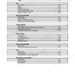
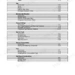
What's Inside This JCB 801, 801 Tracked Manual
| System | Pages | Key Topics |
|---|---|---|
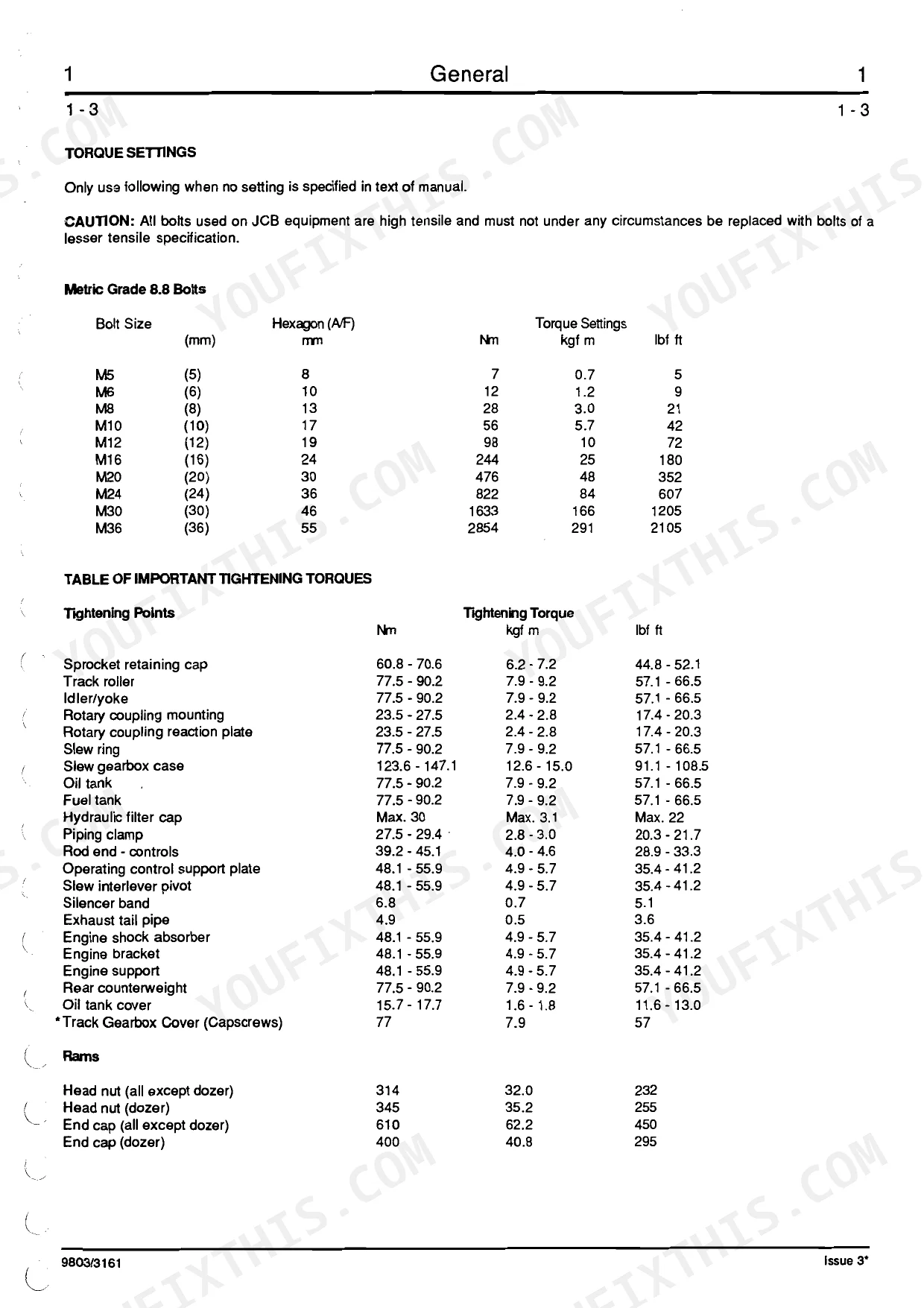
| General | 7-13 | Lubricants & Capacities, Torque Settings, Service Schedules |
| Greasing | 16-20 | - |
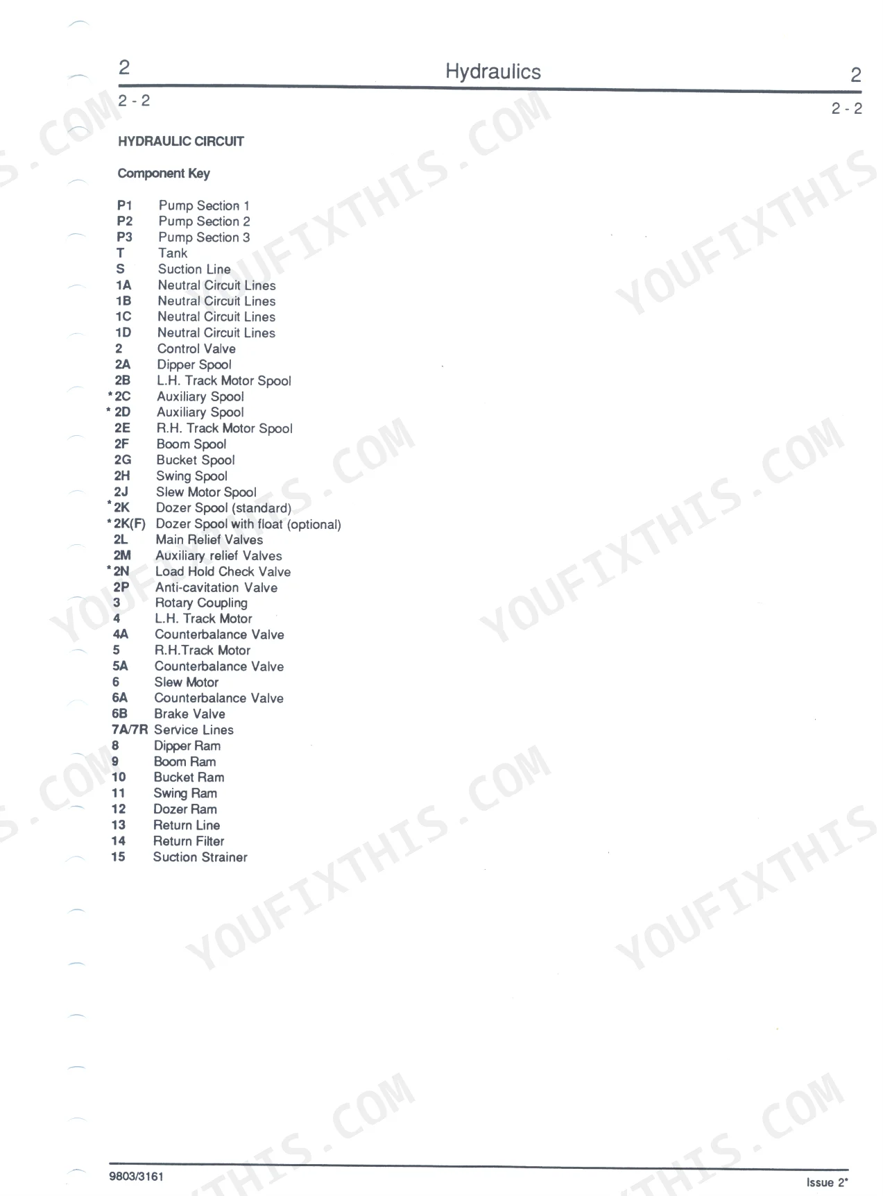
| Hydraulic Circuit | 21-30 | - |
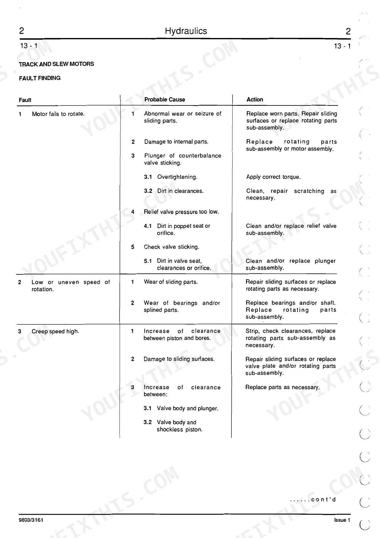
| Track Motor Operation | 31-40 | - |
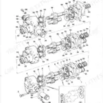
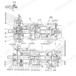
| Hydraulic Pump | 41-57 | - |
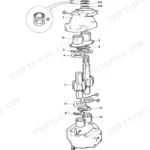
| Slew Motor | 58-63 | - |
| Slew Motor Brake Valve | 64-82 | - |
| Control Valve | 83-90 | - |
| Rams | 91-101 | - |
| Attachments | 102 | - |
| Body and Framework | 103-112 | Front Attachment, Upper Structure |
| Engine | 113-152 | Technical Data, Fuel System, Cylinder Head, Piston and Connecting Rods, Crankshaft |
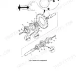
| Gearboxes | 153-170 | Track Gearbox, Slew Gearbox |
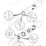
| Track & Running Gear | 171-185 | Tracks, Track Rollers, Idler and Recoil Unit |
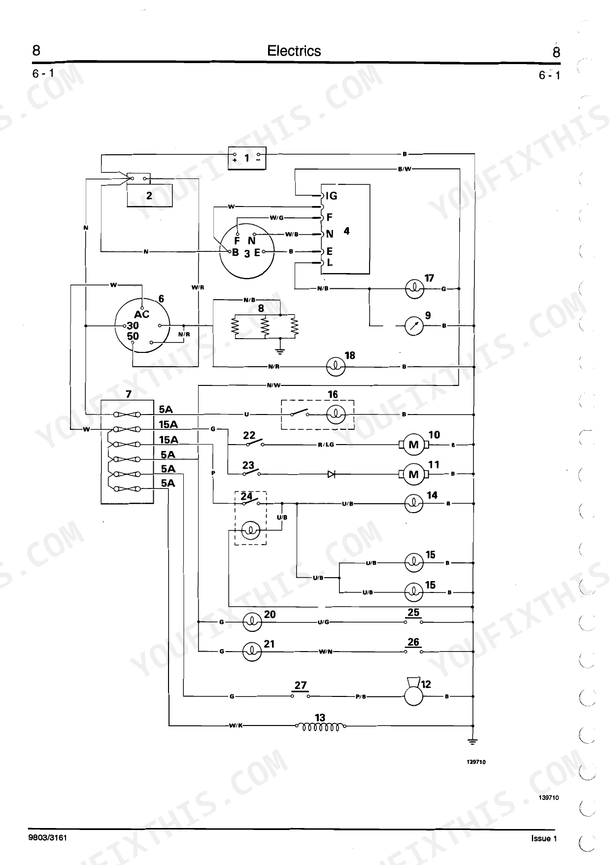
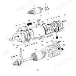
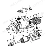
| Electrics | 186-216 | Alternator, Voltage Regulator Operation, Continuity Tests, Starter Motor |
Quick Reference Specifications
| Specification | Value | Page |
|---|---|---|
| Main Relief Valve Adjustment | Adjust the M.R.V. by means of the screw D until the gauge reads 207 bar (3000 lbf/in2) | p. 100 |
| Hydraulic Pump Drive Coupling Torque (Sundstrand) | 44 Nm (4.5 kgf m, 32 lbf ft) | p. 10 |
| Hydraulic Pump Tie Bolts Torque (Sundstrand) | 54-61 Nm (5.5-6.2 kgf m, 40-45 lbf ft) | p. 10 |
| Hydraulic Fitting Adapter (A) Torque (SAE Tube Size 4) | 20-28 Nm (16.5-18.5 lbf ft) | p. 11 |
| Hydraulic Fitting Outer Sleeve Nut (B) Torque (SAE Tube Size 4) | 20-30 Nm (15-21 lbf ft) | p. 11 |
| Fuel Filter Canister Tightening | hand tight and then one quarter turn | p. 121 |
| Inner Air Filter Element Replacement Interval | every third time the outer element is changed | p. 128 |
| Fan Belt Deflection | 5 mm (0.2 in) with 50 N (5 kgf, 11 lbf) finger force | p. 131 |
| Track Gearbox Oil Capacity | 1.6 litres (0.4 UK gal) | p. 153 |
| Track Gearbox Plug Torque | 20-30 Nm (2.0-3.0 kgf m, 15-22 lbf ft) | p. 165 |
| Rubber Track Tension | 10-15 mm (0.4-0.6 in) | p. 174 |
| Battery Voltage | 12V | p. 186 |
JCB 801, 801 Tracked Common Problems This Manual Covers
JCB 801 track slows down or loses power when operating another hydraulic function.
Inspect the hydraulic circuit and main relief valve. Check for leaks around the pump using cardboard, as instructed on page 25. Adjust the main relief valve adjusting screw until the pressure gauge reads 207 bar (3000 lbf/in2). Torque hydraulic fitting adapters to 20-28 Nm (16.5-18.5 lbf ft).
Manual Section: Track and Slew Motors Fault FindingEngine will not start after several attempts or turns over slowly after storage. p. 121
Bleed air from the entire fuel system. Inspect the fuel filter and replace if dirty. Install the new filter canister, tighten it hand tight, and then give it exactly one quarter turn as specified on page 121. Verify the fuel tank contains up to 17.0 Litres (3.75 Gal) of clean diesel.
Manual Section: EngineFrequent fan belt wear, squealing noise, and engine overheating during standard operation. p. 131
Inspect the belt condition and adjust the tension. Check the deflection on page 131. Apply 50 N (11 lbf) of finger force to the belt. Adjust the alternator position until deflection measures exactly 5 mm (0.2 in) to prevent timing case cover damage.
Manual Section: EngineRubber track slips off idler wheel or makes popping noises during travel. p. 174
Clean the undercarriage and inspect the recoil unit. Measure the track tension at the center track roller. Inject grease into the tensioner cylinder until the clearance measures 10-15 mm (0.4-0.6 in) for rubber tracks, following the procedure on page 174. Check the idler wheel for excessive wear.
Manual Section: Track & Running Gear InspectionOil leaking from the final drive or track motor fails to rotate correctly. p. 165
Drain the track gearbox and inspect the magnetic plug for metal shavings. Fill the housing with fresh oil. For machines up to number 649729, add 1.6 Litres (0.35 Gal) of fluid. Secure the drain plug and torque it to 20-30 Nm (15-22 lbf ft) as detailed on page 165.
Manual Section: GearboxesFrequently Asked Questions
How do I bleed the fuel system on a JCB 801 after a no-start?
If the engine fails to start, misfires, or if any part of the fuel system has been disconnected or become empty, you need to bleed the system. Loosen vent screw A on top of the fuel filter, operate the fuel lift pump priming lever X until air-free fuel flows, then tighten screw A. Next, loosen connecting union nuts B, C, and D at the injectors, use the starter key to turn the engine until air-free fuel flows from the connections, and finally tighten the union nuts. Refer to page 5/5 - 7 for the full procedure.
What are the torque specs for JCB 801 track motor or undercarriage bolts?
For track-related components, the torque settings are: Track roller bolts at 77.5 - 90.2 Nm (57.1 - 66.5 Ibf ft), Track Gearbox Cover (Capscrews) at 77 Nm (57 Ibf ft), and Idler wheel assembly bolts to the yoke at 98 Nm (72 Ibf ft). Track Motor cap screws should be tightened to 58-69 Nm (43-51 Ibf ft). Refer to page 1/1-3 for general torque settings and specific component torques.
What are the replacement specifications for hydraulic pump mounts?
When replacing hydraulic pump mounts, ensure to tighten the tie bolts and drive coupling nut to specified torque settings. For Sundstrand pumps, the drive coupling torque is 44 Nm (32 Ibf ft) and tie bolts are 54-61 Nm (40-45 Ibf ft). For Dowty pumps, the drive coupling torque is 54 Nm (40 Ibf ft) and tie bolts are 44-52 Nm (32-38 Ibf ft). Refer to page 1/1-4 for detailed torque settings.
What are the replacement specifications for hydraulic hoses/fittings?
All hydraulic fittings on the JCB 801 use an 'O' ring face seal system. For ADAPTER (A) fittings, torque ranges from 20-28 Nm (16.5-18.5 Ibf ft) for SAE Tube Size 4 to 280-380 Nm (210-280 Ibf ft) for SAE Tube Size 20. For OUTER SLEEVE NUT (B) fittings, torque ranges from 20-30 Nm (15-21 Ibf ft) for SAE Tube Size 4 to 155-175 Nm (114-130 Ibf ft) for SAE Tube Size 16. Refer to page 1/1-5 for detailed torque specifications.
What do I get after purchasing this JCB 801, 801 Tracked Excavator manual?
Immediate download of the complete 216-page searchable Service Manual. Access it on any device, from a laptop at your desk to a phone in the field.
Can I print specific sections of this manual?
Yes. The PDF has no DRM restrictions, so print any page or section you need for your shop. Works with any standard printer.
Does this JCB 801, 801 Tracked Excavator manual include wiring diagrams?
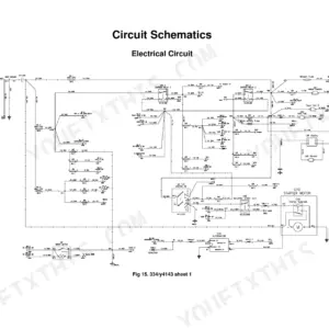
Included. The JCB 801, 801 Tracked Excavator Service Manual covers complete wiring harness diagrams, electrical circuits, and connector pinouts.
Reviews
There are no reviews yet.