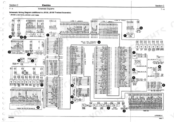
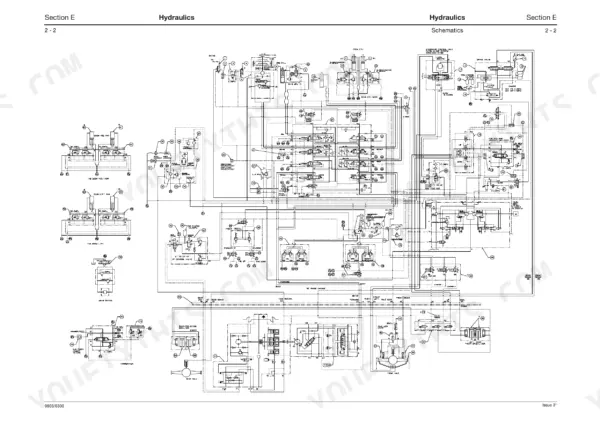
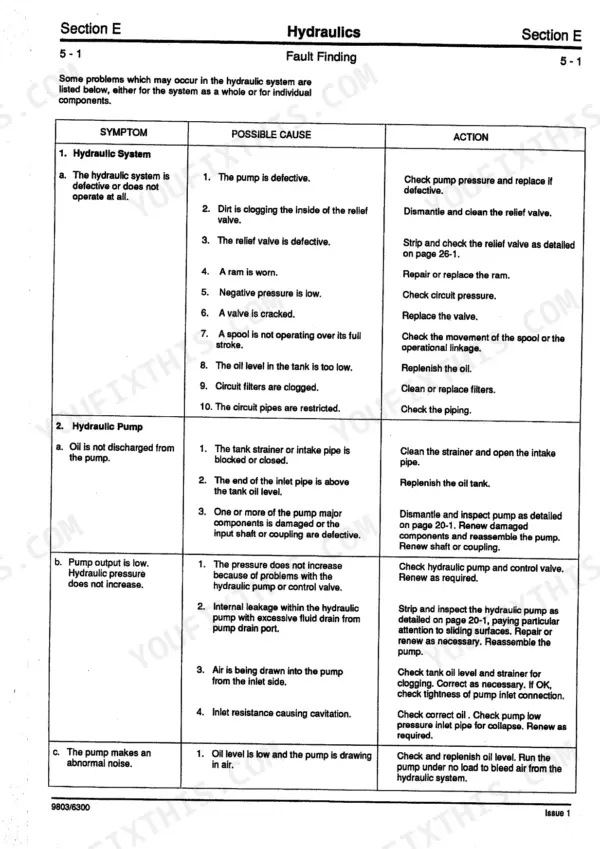
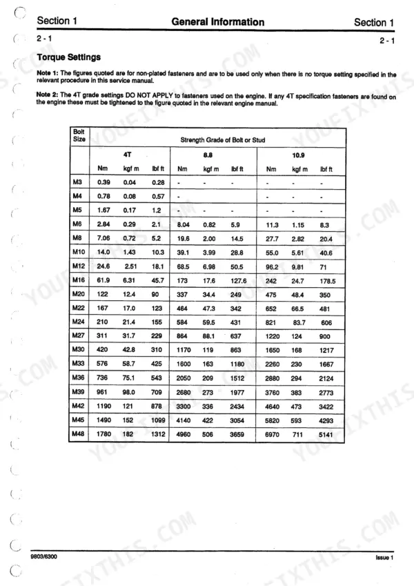
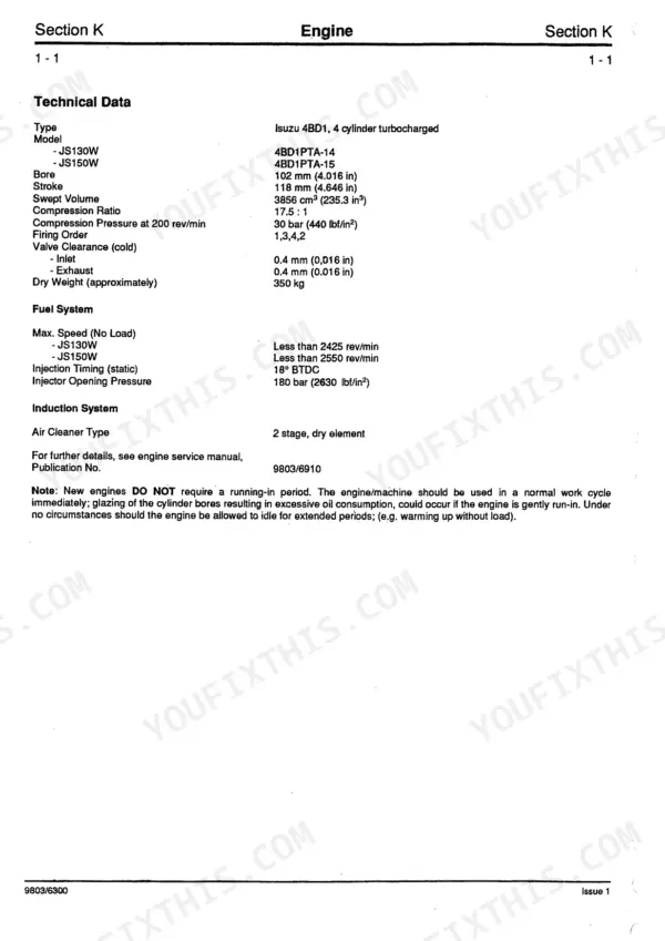
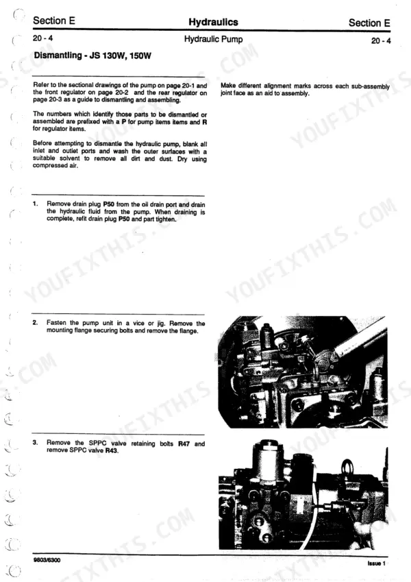
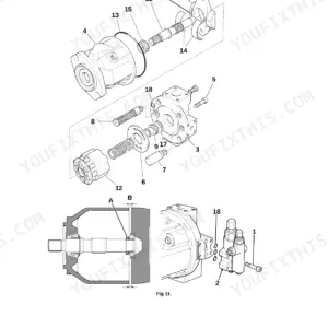
When your wheeled digger goes down hard, this 414-page JCB JS130W, JS150W Service Manual PDF (OEM #9803/6300) breaks down the complete hydraulic, transmission, and electrical systems for your excavator. Massive hydraulic schematics cover the rotary coupling and swing motor, and detailed wiring diagrams help trace elusive electrical faults. Open to the troubleshooting sections to find exact fault-finding charts, factory torque settings, and step-by-step drive gearbox rebuild instructions. Plan your routine maintenance by the book, knowing exactly when to renew the P20 oil seal after 3000 hours of operation or how to safely unscrew the hydraulic filler cap 10 degrees to release tank pressure before wrenching. Guesswork only leads to blown seals and wrecked components. Download this bookmarked file directly to your tablet and bring it right to the shop floor.
Complete the set for your JS130W, JS150W
Other edition of this manual
What's Inside This Manual
| System | Pages | Key Topics |
|---|
| General Information | 3-16 | Machine Identification, Torque Settings, Service Tools (Section: C Electrics, E Hydraulics, F Transmission), Sealing and Retaining Compounds |
| Care & Safety | 17-22 | Safety Notices, Operating Safety, Maintenance Safety |
| Optional Equipment | 67 | Rockbreaker |
| Body & Framework | 68 | |
| Electrics | 69-84 | Schematic Diagrams |
| Controls | 85-88 | Steering Column, Upper Steering Assembly, Lower Steering Assembly, Steering Control Unit, Column Hinge |
| Hydraulics | 89-246 | Fault Finding, Pressure Testing, Circuit Descriptions, Hydraulic Pump, Valves, Steering Control Unit, Rotary Coupling, Swing Motor |
| Transmission | 247-410 | Drive Gearbox, Swing Gearbox, Front Axle, Rear Axle |
| Brakes | 411-412 | Drive Brakes, Parking Brake, Swing Brakes |
Quick Reference Specifications
| Specification | Value | Page |
|---|
| All Models |
| Hydraulic system reset procedure (Releasing Tank Pressure) | 1. Position the machine on level ground with the bucket and dipper rams fully extended and the boom lowered to rest the attachment on the ground. 2. Stop the engine. 3. Remove the starter key. 4. Use the small Allen key supplied in the tool kit to loosen the spring-loaded retaining pin at the side of filler cap C. 5. Rotate the bolt 1/4 turn anti-clockwise against the spring and hold there. 6. Carefully unscrew the filler cap C approximately 10° until the pressure starts to release. 7. Remove the Allen key. 8. Leave the filler cap C at this setting to allow the pressure to release fully. 9. Verify by carefully removing the filler cap. | p. 35 |
| Oil Seal (P20) replacement interval | Renew after 3000 hours of operation, or if damaged | p. 144 |
| O-rings replacement interval (general) | Renew after 3000 hours of operation, or if damaged | p. 207 |
| Hydraulic Hoses replacement condition | Replace if damaged end fittings, chafed outer covers, ballooned outer covers, kinked or crushed hoses, embedded armouring in outer covers, or displaced end fittings are found. | p. 22 |
| Fuel Filter Element tightening | Hand-tighten onto filter head, then use a chain wrench to tighten by a further 1/3 turn | p. 53 |
| Hydraulic Return Filter Element replacement interval | 100 hours (100% usage), 200 hours (40% usage), 300 hours (20% usage), 400 hours (10% usage) | p. 65 |
| Pressure Gauge (high pressure) | 0-400 bar (0-6000 lbf/in2) | p. 7 |
| Pressure Gauge (low pressure) | 0-70 bar (0-1000 lbf/in2) | p. 7 |
| JS130W |
| Oil Seal (2) replacement interval | Renew after 3000 hours of operation, or if damaged | p. 207 |
| O-rings replacement interval | Renew after 3000 hours of operation, or if damaged | p. 207 |
| JS150W |
| Clearance (D-d) between piston and cylinder bore (recommended value for renewal) | 0.058 mm (0.002 in.) | p. 219 |
| Play between the piston and shoe (d) (recommended value for renewal) | 0.3 mm (0.012 in.) | p. 219 |