


Part of the JCB Repair Manuals.
This is the JCB Robot 160, 170 and 180T Service Manual (publication 9803/8520 issue 14), a 308 page factory workshop manual for these skid steer loaders produced from 1998 to 2005. It covers both wheeled machines and the tracked 180T, with 100 Series and 400 Series engine data.The manual carries the repair coverage a technician needs: general information and torque settings, electrics, controls, a large hydraulics section with pressure testing, transmission, brakes, tracks and engine removal and replacement. Dismantling and assembly steps are given for the major components, along with machine identification details for ordering the right parts.Use it to diagnose weak hydraulics, drive and brake faults or electrical problems, and to carry out overhauls to factory specification. It suits owners, restorers and independent workshops servicing these Robot loaders.
What's Inside This JCB ROBOT 160, ROBOT 170, ROBOT 180T Manual
| System | Pages | Key Topics |
|---|---|---|
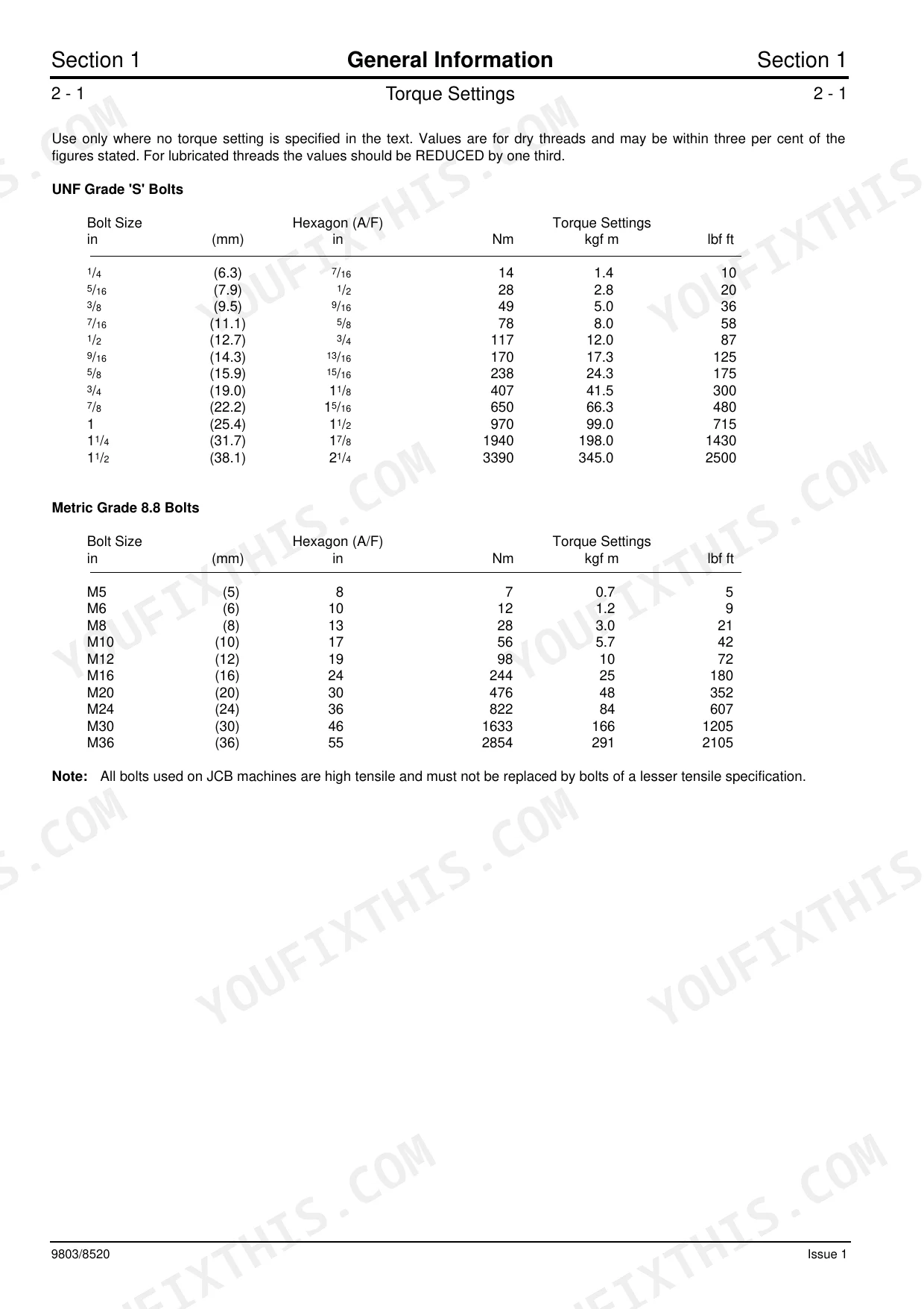
| General Information | 3-19 | Identifying Your Machine, Torque Settings (Unsealed Hoses and Adapters, O’ Ring Face Seal System, Torque Stop’ Hose System) |
| Care & Safety | 20-27 | Contents, Safety Notices, General Safety, Operating Safety, Maintenance Safety, Safety Decals |
| Attachments | 56-61 | Quick Release Couplings, Connecting/Disconnecting Hoses, Shovels (6-In-1 Shovels), Pallet Forks, Manure/Silage Fork with Top Grab, Attachment Frame |
| Body & Framework | 62-76 | Seat and Pump Cover (Seat Removal and Replacement, Pump Cover Removal and Replacement), Windows (Front Screen Removal and Replacement, Glazing) |
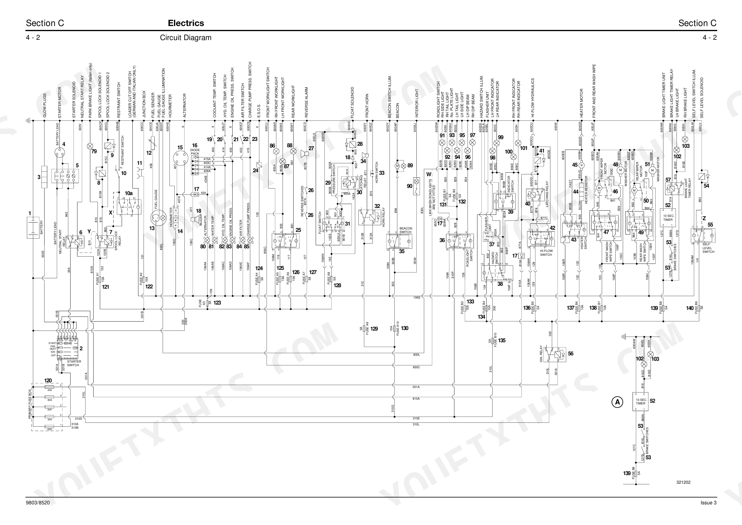
| Electrics | 77-117 | Technical Data (Light Bulbs, Circuit Protection, Sensing Switches) |
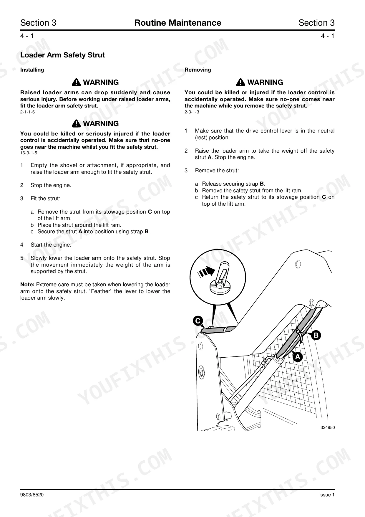
| Controls | 118-126 | Safety Restraint (Removal and Replacement, Machines, 180T Machines) |
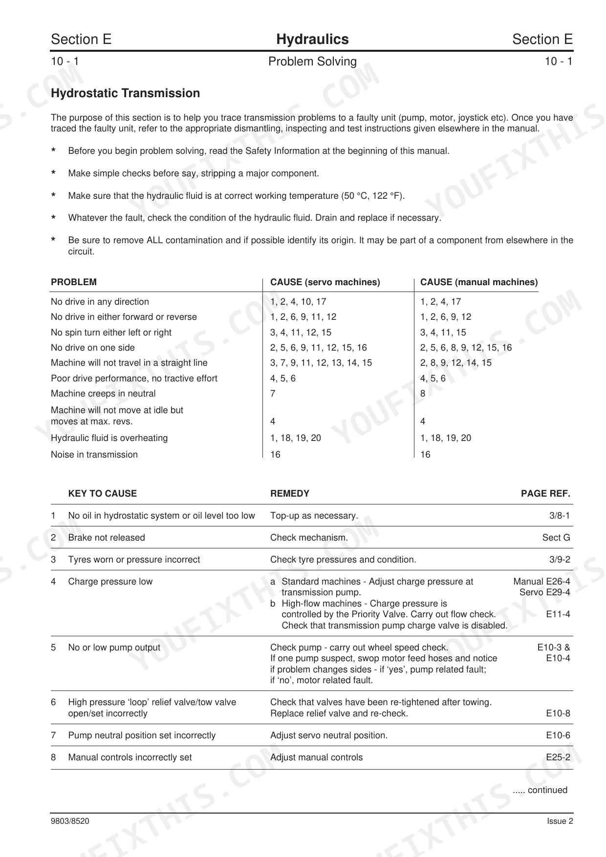
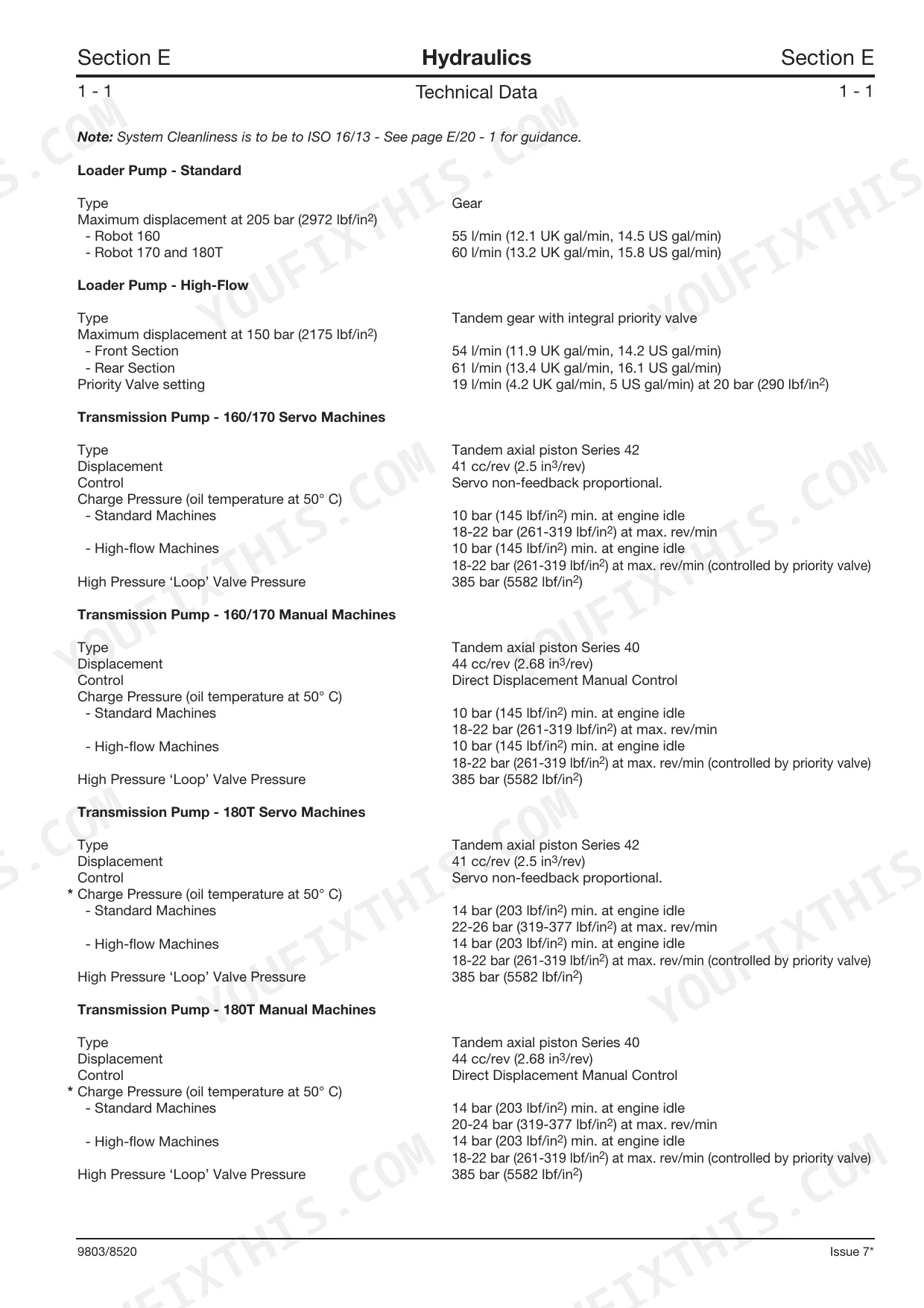
| Hydraulics | 127-268 | Pressure Testing (Main Relief Valve, Power Managemant System Fitted to 180T with Servo Transmission Controls)), Pumps - General (Pump/Engine Couplings, Start-Up Procedure) |
| Transmission | 269-280 | Tyres and Wheels (Roadwheels), Hubs and Driveshafts (Wheel Hub Assembly, Left Hand Drive Shaft), Drive Chains (Removal and Replacement, Adjustment), Tyre Pressures |
| Brakes | 281-285 | Testing the Parking Brake, Parking Brake, Manual Override Lever, Parking Brake Mechanism (Dismantling and Assembly) |
| Tracks | 286-303 | Track Damage, Track Repair, Track (Removal and Replacement), Motor (Removal and Replacement), Idler Wheels and Rollers (Removal and Replacement) |
| Engine | 304-308 | Technical Data (Up to Machine No. 681290, From Machine No. 681291, Series Turbo Diesel Engine), Removal and Replacement |
Quick Reference Specifications
| Specification | Value | Page |
|---|---|---|
| UNF Grade 'S' Bolts (1/4 in) | 14 Nm | p. 5 |
| Metric Grade 8.8 Bolts (M5) | 7 Nm | p. 5 |
| BSP Adapters with Bonded Washers (1/8 in) | 20 Nm | p. 6 |
| SAE Adapters with ‘O’ rings (7/16 in) | 20 Nm | p. 6 |
| Hydraulic Coned BSP Hoses (1/8 in) | 14 Nm | p. 6 |
| ‘O’ Ring Face Seal System (Adaptors screwed into valve blocks, 1/4” BSP) | 18 Nm | p. 7 |
| Hydraulic filter element replacement | 5 micron rated filter element, part number 581/18020 | p. 201 |
| Hydraulic filter canister torque | hand tight only | p. 41 |
| Fuel filter element center bolt torque | 8-11 Nm | p. 51 |
| Wheel nut torque (up to machine no. 680678) | 244 Nm | p. 271 |
| Wheel nut torque (from machine no. 680679) | 220 Nm | p. 271 |
| Working Lights wattage | 55W (Halogen) | p. 78 |
JCB ROBOT 160, ROBOT 170, ROBOT 180T Common Problems This Manual Covers
Weak, slow or intermittent hydraulics
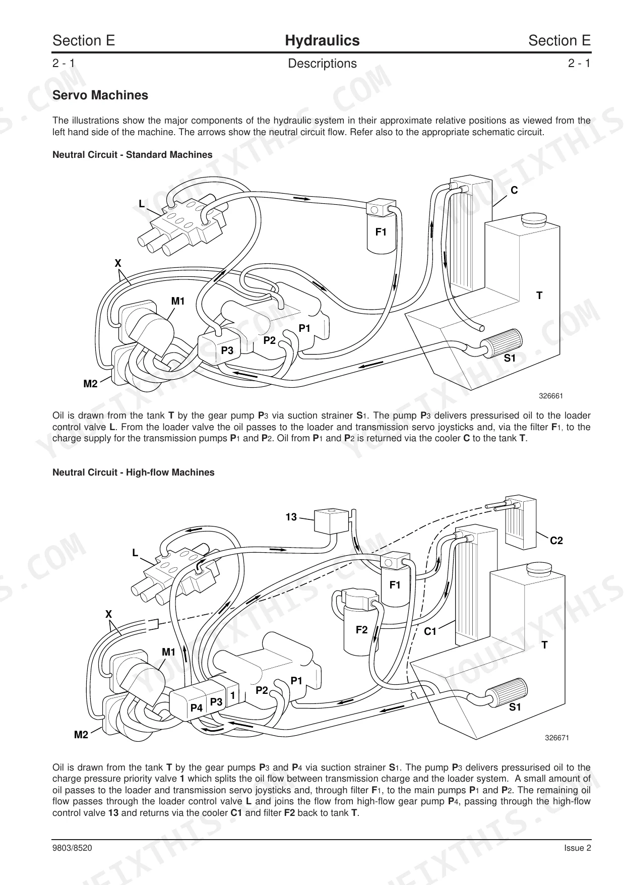
Poor loader or auxiliary performance often traces to fluid level, a clogged filter, or valve and pump wear. The Hydraulics section covers pressure testing, including the main relief valve and the power management system on servo transmission machines.
Manual Section: Hydraulics p. 127Engine will not start or stalls under load
Hard starting or stalling points to fuel, engine or charging faults. The Engine section gives technical data and removal and replacement procedures, with data split for machines up to and from machine number 681291.
Manual Section: Engine p. 304Abnormal drive or slow travel
Drive problems on these loaders can come from the transmission, drive chains, hubs or driveshafts. The Transmission section covers roadwheels, wheel hub assembly, drive shafts, drive chain removal, replacement and adjustment.
Manual Section: Transmission p. 269Electrical faults and warning lights
Warning lights, dead circuits or control failures usually mean a switch, connector or wiring fault. The Electrics section gives technical data covering light bulbs, circuit protection and sensing switches.
Manual Section: Electrics p. 77Parking brake will not hold
A parking brake that drags or fails to hold needs testing and adjustment. The Brakes section covers testing the parking brake, the manual override lever and dismantling and assembly of the parking brake mechanism.
Manual Section: Brakes p. 281Track damage on the 180T
Cut or thrown tracks and worn rollers are a recurring concern on the tracked 180T. The Tracks section covers track damage, track repair, track and motor removal and replacement, and idler wheels and rollers.
Manual Section: Tracks p. 286Frequently Asked Questions
Which models does this manual cover?
It is the service manual for the JCB Robot 160, 170 and 180T skid steer loaders from 1998 to 2005, covering both the wheeled machines and the tracked 180T.
Where do I find torque specifications?
The General Information section lists torque settings, including UNF Grade S bolts, Metric Grade 8.8 bolts and the hose and adapter systems, for tightening fasteners correctly. p. 3
Does it include hydraulic pressure testing?
Yes. The large Hydraulics section covers pressure testing, the main relief valve and the power management system fitted to 180T machines with servo transmission controls. p. 127
How is the manual delivered?
It is delivered instantly as a download. The link is available right after checkout, so you can start using it straight away.
What format is this manual in?
Instant PDF download. The full 308-page searchable Service Manual lands the moment payment clears. Open it on a laptop, tablet, or phone right on the shop floor.
Is this JCB ROBOT 160, 170, 180T Service Manual printable?
Yes. Print as many copies as you want, with no restrictions. Plenty of mechanics print just the section they need and carry it to the shop floor.
Does this JCB ROBOT 160, 170, 180T Service Manual cover the hydraulic system?
Yes. It includes full hydraulic schematics with flow diagrams, valve configurations, and pressure specifications.
Reviews
There are no reviews yet.