


Part of the Case Repair Manuals.
All 148 pages of this Case Backhoe Service Manual (OEM #SM30A) focus on one machine family: the B-1, B-1 Heavy Duty, 43-1, 43-2, 3122, and 3142 International Back Hoes, covering every hydraulic circuit from factory schematics to field repair. You get complete cylinder teardown procedures for lift, dig, bucket, swing, and stabilizer units, plus a full valve section covering the control valve bank, cross line relief valves, flow control and cushion valves, and the proportional flow divider. The Systems section lays out hydraulic schematic diagrams for each model variant, tracing oil flow from pump through every spool and into each working cylinder. Torque your 7/16-20 JIC 37° flared fittings to 1.38-2.76 kgm, and note the standard Type 5 1/4-inch bolt range of 1.24-1.26 kgm. No more chasing hydraulic leaks with hunches and a parts-counter phone call. Bookmarked by section; search any spec by keyword, open it on your tablet, and get back on the machine.
What's Inside This Case B-1, 43-1, 43-2, 3122, 3142 Manual
| System | Pages | Key Topics |
|---|---|---|
| General | 5-26 | Service Tools, Service Parts, Bolt Identification Chart, Standard Torque Data, Seals and Packing, Hydraulic Theory |
| Cylinders | 27-62 | Lift Cylinder, Dig Cylinder, Bucket Cylinder, Swing Cylinders, Stabilizer Cylinders |
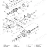
| Valves | 63-108 | Control Levers, Control Valve, Cross Line Relief Valves, Flow Control & Cushion Valve, Relief Valve Manifold, Flow Control Valve, Check Valve, Proportional Flow Divider |
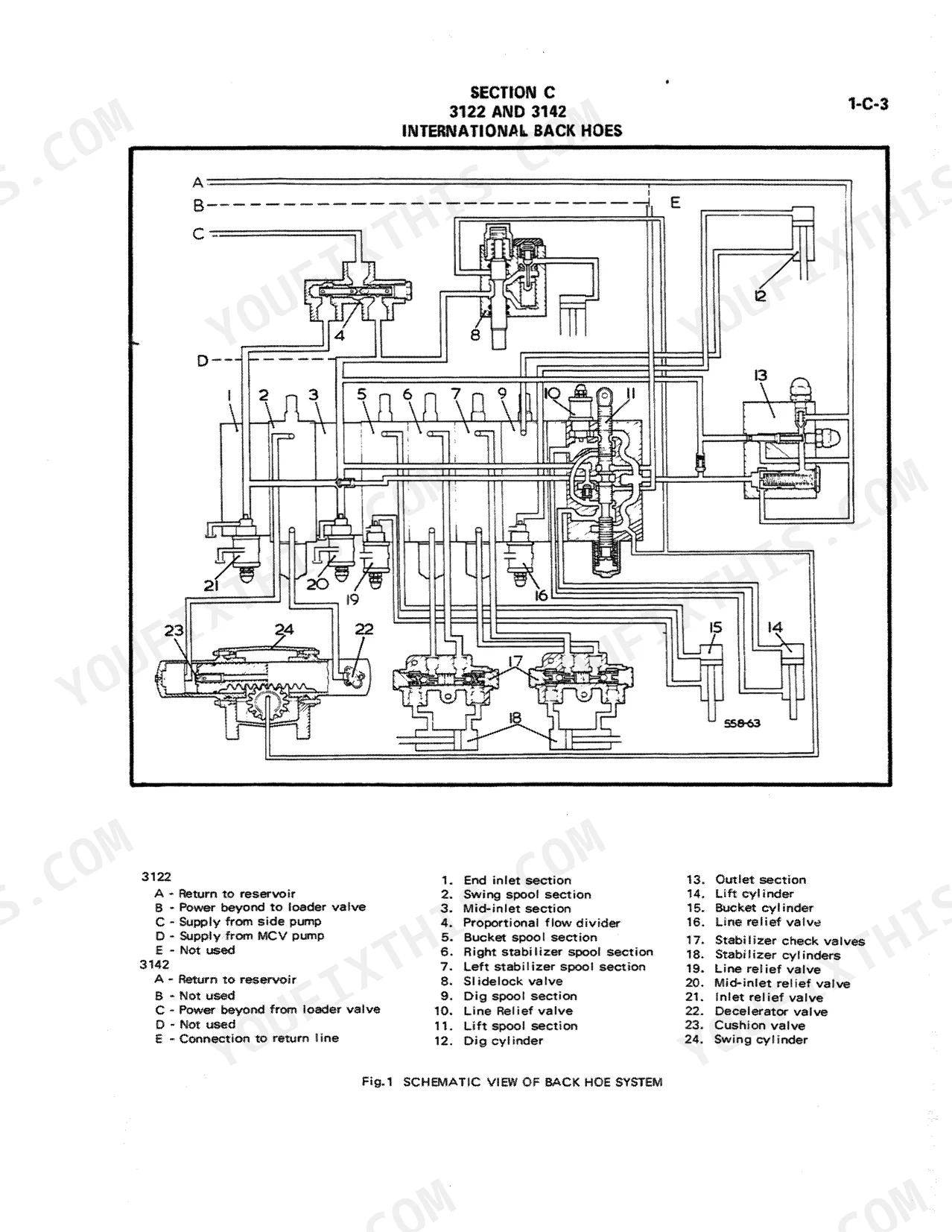
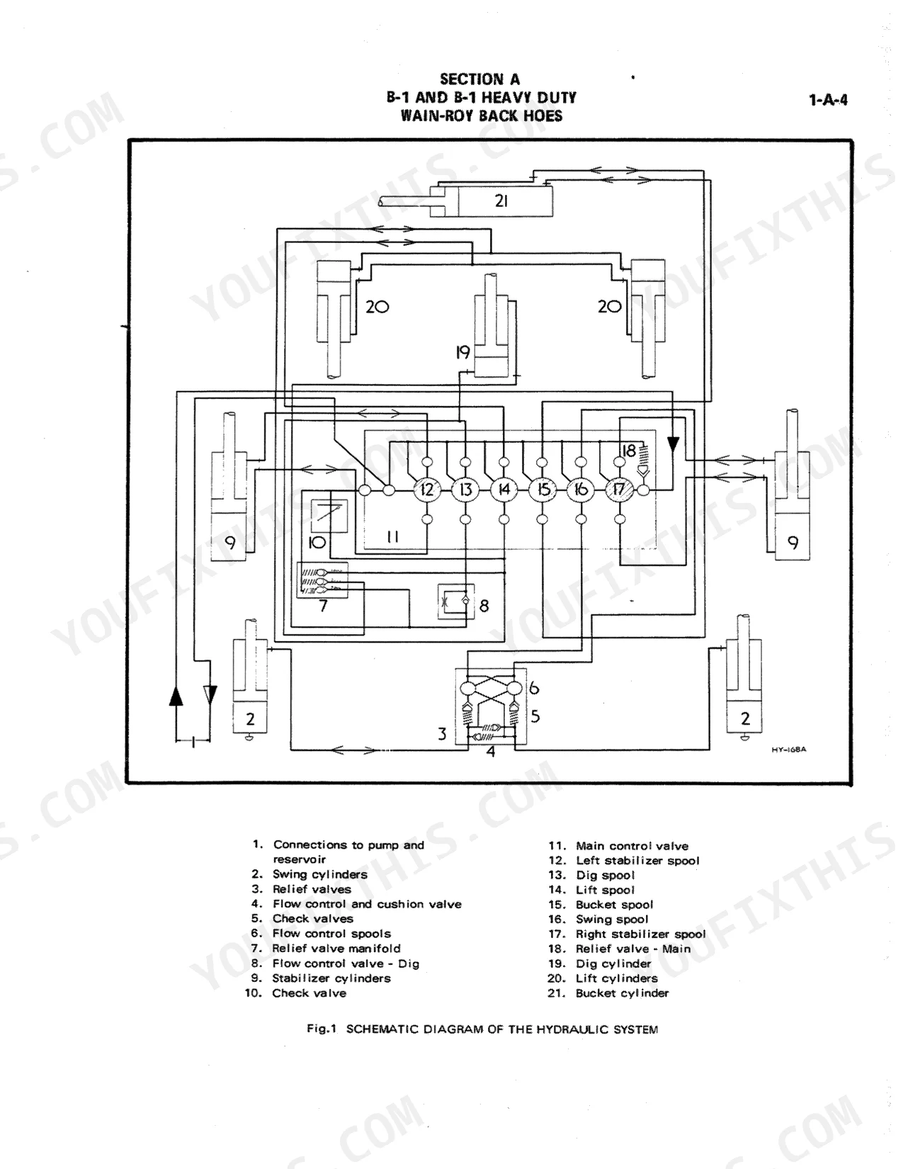
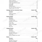
| Systems | 109-116 | Description (General), Oil Flow Indicators (High Pressure, Return Flow, Reversing Flow According to Control Valve), Section a B-1 and B-1 Heavy Duty Wain-Roy Back Hoes |
| Reservoirs and Filters | 117-124 | Reservoir, Filters, Suction Strainer, Drain Plug, Filter Cap, Gasket |
| Mainframe | 125-148 | Bucket, Dipperstick, Boom, Lift Arm, Stabilizers, Swing Mechanism |
Quick Reference Specifications
| Specification | Value | Page |
|---|---|---|
| All Models | ||
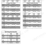
| JIC 37° FLARED FITTINGS torque (Pipe Size 1/4, Thread Size 7/16 - 20) | 1.38-2.76 kgm (10-20 lbft) | p. 7 |
| Seal replacement interval | whenever a unit is dismantled | p. 9 |
| JIC 37° SEAT Torque (7/16 - 20 thread) | Min 0.83 kgm to Max 1.38 kgm | p. 7 |
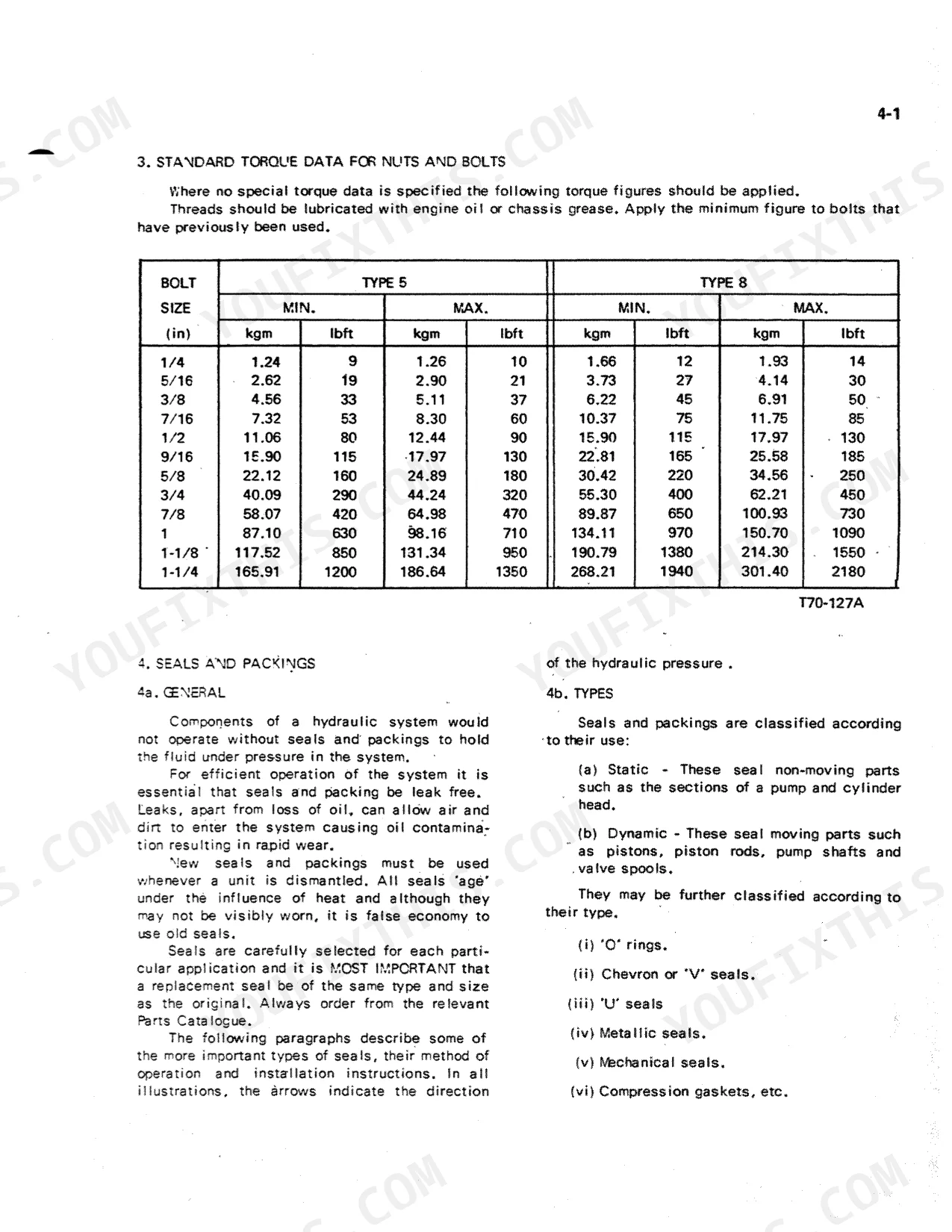
| Standard Bolt Torque (Type 5, 1/4" bolt) | Min 1.24 kgm to Max 1.26 kgm | p. 9 |
| Pins and Bushes Clearance | 0.30 mm | p. 20 |
| B-1 | ||
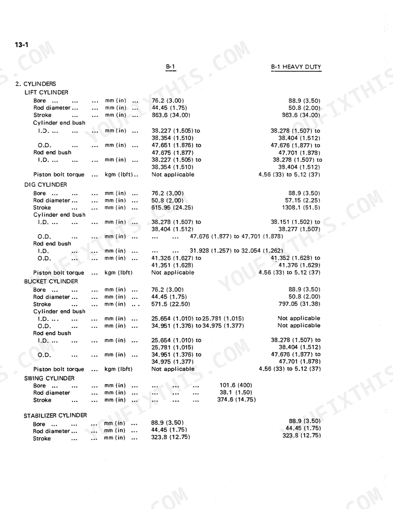
| Lift Cylinder Bore | 76.2 mm | p. 18 |
| B-1 Heavy Duty | ||
| Lift Cylinder Piston Bolt Torque | 4.56 kgm to 5.12 kgm | p. 18 |
| B-1, B-1 Heavy Duty | ||
| Relief Valve Manifold Lift Pressure Setting | 70.3 kg/cm2 | p. 19 |
| 43-1, 43-2 | ||
| Control Valve Main Relief Valve Setting | 137.1 kg/cm2 to 144.1 kg/cm2 | p. 22 |
| 3122 | ||
| Lift Cylinder Bore | 101.6 mm | p. 23 |
| 3122, 3142 | ||
| Swing Mechanism Backlash | 0.02 mm to 0.33 mm | p. 25 |
Case B-1, 43-1, 43-2, 3122, 3142 Common Problems This Manual Covers
Backhoe attachment won't dig or lift, pump running but no cylinder movement
Inspect the hydraulic coupling between pump and engine shaft for damage or misalignment. Check all JIC flared fittings at the control valve inlet; torque 7/16–20 thread fittings to 0.83–1.38 kgm per page 7. Remove and inspect the control valve per page 63: look for stuck spools, worn seals, and contamination. On 43-1 and 43-2 models, verify main relief valve is set to 137.1–144.1 kg/cm2 per page 22. Replace any seals found damaged during disassembly.
Manual Section: Valves p. 63Pins and bushes worn excessively, backhoe arm has visible slop and imprecise bucket placement
Measure pin-to-bush clearance at all pivot points: maximum allowable clearance is 0.30 mm per page 20. Clearance beyond this causes sloppy control and accelerated wear. Remove pins per page 125, inspect for scoring and ovality, and replace any pin or bush that exceeds limit. Check all clevis pins, welds, and castings while apart per page 6. Apply lubrication to all fittings before reassembly.
Manual Section: Mainframe p. 125Swing mechanism on 3122 or 3142 drifts or jerks during side-to-side movement
Measure swing mechanism backlash per page 25: acceptable range is 0.02–0.33 mm. Backlash outside this range causes jerky or uncontrolled swing. Inspect the swing frame and slide frame; maximum slide frame stop face clearance is 1.53 mm per page 25. Remove the swing mechanism per page 125 and inspect gear teeth and wear surfaces. Check cushion valve function per page 63 — a faulty cushion valve causes end-of-stroke shock that accelerates swing wear.
Manual Section: Mainframe p. 25Oil leaking from cylinder rod seals, hydraulic fluid visible on boom or dipperstick tubes
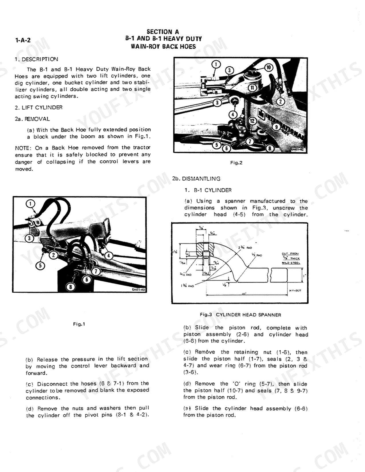
Clean the area and identify the leaking cylinder: lift, dig, bucket, swing, or stabilizer. Remove the cylinder per the applicable procedure starting page 27. Inspect the rod for scoring deeper than surface finish — a scored rod cuts new seals immediately. Replace all seals and packing during any disassembly per page 9. Inspect oil pipes and hoses for chafing or fitting damage per page 6. Reinstall and test on the machine per page 16, checking for pressure fall over a 5-minute hold.
Manual Section: Cylinders p. 27Frequently Asked Questions
Torque specs for CASE 43-1 hydraulic pump bolts?
The manual does not provide specific torque specifications for hydraulic pump bolts for the CASE 43-1. For general nuts and bolts, it states that threads should be lubricated with engine oil or chassis grease, and the minimum figure should be applied to bolts that have been previously used. Refer to the standard torque data table on page 9 for general bolt sizes. p. 9
What are the replacement specifications for Hydraulic fluid filter?
The manual states that the 43-1 reservoir contains a suction strainer and a micronic filter for hydraulic fluid. However, for the replacement specifications of these filters, it explicitly directs the user to refer to the Operator's Manual. p. 120
How do you fix case backhoe hydraulic fluid turning cloudy or showing metal shavings, bucket response sluggish?
Drain the reservoir completely and inspect fluid for contamination. Remove and inspect the suction strainer per page 117. Replace the hydraulic fluid filter as directed by your Operator's Manual (page 120). Clean the reservoir interior before refilling. Check all JIC 37° flared fittings at the pump inlet and torque to 1.38–2.76 kgm (10–20 lb·ft) per page 7. Refill with clean fluid and cycle all functions to purge air. p. 117
How do you fix hydraulic system losing pressure under load, lift arm drifts down when controls are released?
Check for internal cylinder leakage first: isolate the lift cylinder on the machine per page 16 and measure pressure fall over 5 minutes. If leakage exceeds spec, remove the cylinder and inspect piston seals, replacing all seals whenever the unit is dismantled per page 9. On B-1 and B-1 Heavy Duty models, verify relief valve manifold lift pressure is set to 70.3 kg/cm2 per page 19. A collapsed suction hose will mimic this symptom — inspect it visually per page 13. p. 16
What do I get after purchasing this Case B-1 & variants manual?
You get a 148-page searchable PDF that downloads instantly after checkout. Open it on your laptop, tablet, or phone, and bring it right to the shop floor.
Can I print specific sections of this Service Manual?
The PDF is DRM-free. Print whatever sections you need to take out to the shop. Standard letter or A4 paper works.


Reviews
There are no reviews yet.