
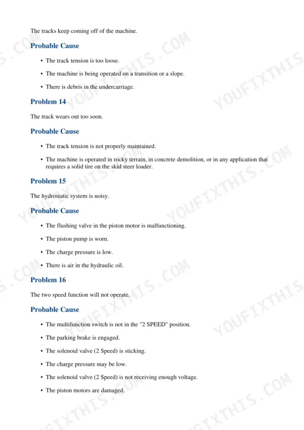
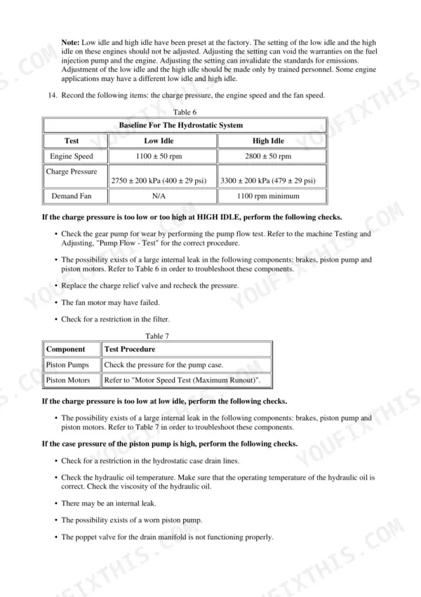
This is the factory repair manual for the Caterpillar 287C Multi Terrain Loader, serial prefix MAS00001-UP, with the 3044C engine. 3438 pages of testing and adjusting, specifications, and disassembly and assembly work: hydrostatic pumps and motors, the work tool hydraulic circuit in standard and High Flow XPS trim, the 3044C top end, undercarriage bogies and track drive, and the monitoring system with its MID/CID/FMI fault codes. Real numbers you can put a gauge against - main relief at 23000 ± 700 kPa (3335 ± 102 psi) on standard flow machines, lift cylinder RAISE at 4.7 ± 0.5 seconds. Your download is a ZIP: the full book plus four separate schematic sheets, three electrical and one hydraulic.
What's Inside This Caterpillar 287C Repair Manual
| System | Pages | Key Topics |
|---|---|---|
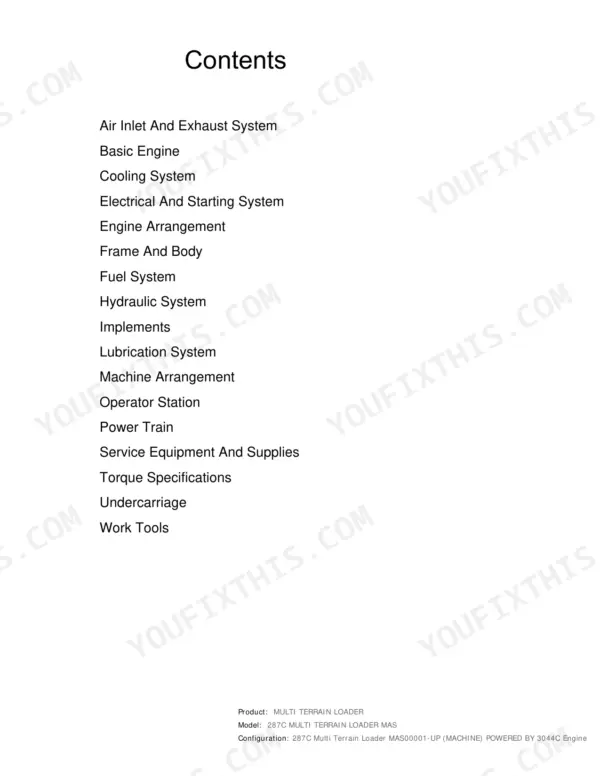
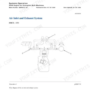
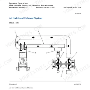
| Air Inlet and Exhaust System | 1-75 | Turbocharger - Inspect, Exhaust Temperature - Test, Air Cleaner, Exhaust Manifold, Inlet Manifold, Muffler |
| Basic Engine | 76-708 | Finding Top Center Position for No. 1 Piston, Fuel Injection Nozzle - Test, Engine Crankcase Pressure (Blowby) - Test, Compression - Test, Engine Valve Lash - Inspect/Adjust, Valve Depth - Inspect |
| Cooling System | 709-848 | Engine Oil Cooler - Inspect, Water Temperature Regulator - Test, Mid 039 - Cid 1076 - Fmi 03, Mid 039 - Cid 1076 - Fmi 05, Mid 039 - Cid 1076 - Fmi 06, Radiator and Oil Cooler Mounting |
| Electrical and Starting System | 849-1359 | Location of Electrical Components, Electrical Input Components, Electronic Control Module, Electrical Output Components, Data Link, Electrical System |
| Engine Arrangement | 1360-1436 | Engine Design |
| Frame and Body | 1437-1451 | Machine Frame and Mounting, Engine Enclosure, Lift Arm Cylinder and Mounting |
| Fuel System | 1452-1621 | Governor Control, Air in Fuel - Test, Fuel Injection Nozzle - Test, Fuel Injection Timing - Check - Distributor Pump, Fuel Quality - Test, Mid 039 - Cid 0096 - Fmi 03 |
| Hydraulic System | 1622-2266 | General Information - High Flow, General Information - Standard Flow, Gear Pump - Charge Oil, Piston Pump (Work Tool) - If Equipped, Control Valve (Work Tool) - Standard Flow, Control Manifold and Solenoid (Work Tool Positioner) - If Equipped |
| Implements | 2267-2307 | Lift Arms - Remove - Vertical Lift, Lift Arms - Install - Vertical Lift |
| Lubrication System | 2308-2395 | Engine Crankcase Pressure (Blowby) - Test, Engine Oil Pressure - Test, Excessive Engine Oil Consumption - Inspect, Increased Engine Oil Temperature - Inspect, Engine Oil Pump - Inspect, Crankcase Breather |
| Machine Arrangement | 2396-2413 | Service Intervals, Heating and Air Conditioning Service Publications, Symptom Troubleshooting |
| Operator Station | 2414-2935 | Monitoring System, Display Module, Input Components, Output Components, Data Link, Warning Operation |
| Power Train | 2936-3235 | Hydrostatic System, Piston Pump (Hydrostatic), Piston Motor (Hydrostatic), Machine Preparation, Visual Inspection, Operational Checks |
| Service Equipment and Supplies | 3236-3252 | Cab Pressurization and Filtration System, Manifold Gauge Set (Refrigerant), Heating and Air Conditioning Service Publications, Required Tools, Fuel Priming Pump and Primary Filter (Water Separator) |
| Torque Specifications | 3253-3302 | Metric (ISO) Fasteners, English (SAE) Fasteners, Ground Engaging Tool (G.E.T.) Fasteners, Installation of Fittings, Straight Thread O-Ring Fittings, Plugs |
| Undercarriage | 3303-3429 | Axle (Front), Axle (Rear), Bogie Suspension, Bogie Wheel, Track Drive, Sprocket |
| Work Tools | 3430-3438 | Quick Coupler, Quick Coupler - Remove and Install - Hydraulic |
Quick Reference Specifications
| Specification | Value | Page |
|---|---|---|
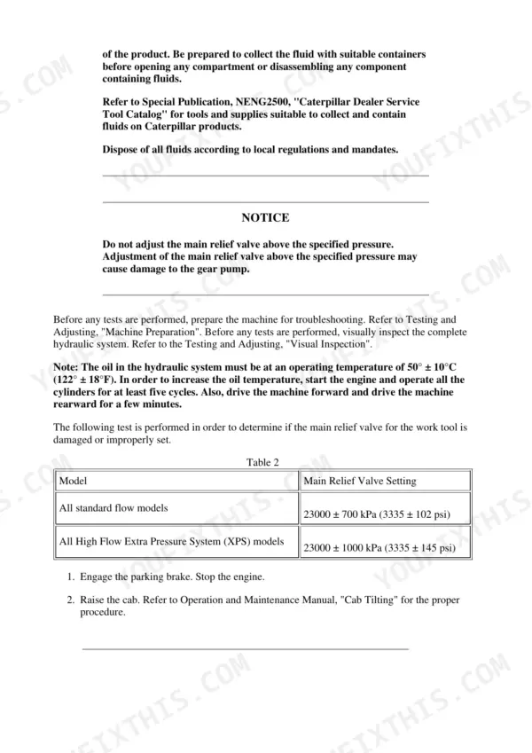
| Main relief valve pressure (standard flow) | 23000 ± 700 kPa (3335 ± 102 psi) | p. 1770 |
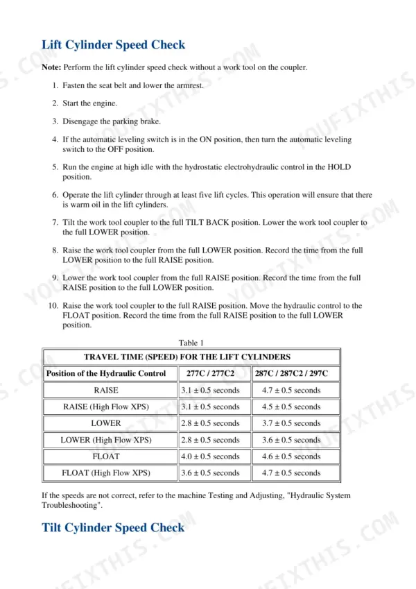
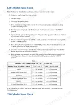
| Lift cylinder Raise time | 4.7 ± 0.5 seconds | p. 1751 |
| Lift cylinder Lower time | 3.7 ± 0.5 seconds | p. 1751 |
| Lift cylinder Float time | 4.6 ± 0.5 seconds | p. 1751 |
| Lift cylinder Raise time, High Flow XPS | 4.5 ± 0.5 seconds | p. 1751 |
| Tilt cylinder Tilt Forward time | 2.5 ± 0.5 seconds | p. 1752 |
| Hydraulic oil test temperature | 50 ± 10°C (122 ± 18°F) | p. 1750 |
| Pilot system pressure | 3500 ± 200 kPa (500 ± 30 psi) | p. 1789 |
| Charge pressure | 900 ± 100 kPa (130 ± 15 psi) | p. 1785 |
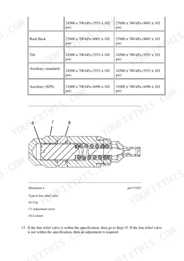
| Line relief valve pressure, lift (standard flow) | 24500 ± 700 kPa (3553 ± 102 psi) | p. 1781 |
| Line relief valve pressure, lift (High Flow XPS) | 27600 ± 700 kPa (4003 ± 102 psi) | p. 1781 |
| Main relief valve setting (High Flow XPS tolerance) | 23000 ± 1000 kPa (3335 ± 145 psi) | p. 1770 |
Caterpillar 287C Common Problems This Manual Covers
Loader loses drive power, one track drags or quits moving entirely
Start with the Power Train chapter's Machine Preparation, Visual Inspection, and Operational Checks before pulling anything apart. It then covers the hydrostatic system through the Piston Pump (Hydrostatic) and Piston Motor (Hydrostatic) sections, so you can isolate a charge pressure problem or a failing drive motor on one side instead of guessing.
Manual Section: Power Train - Testing and Adjusting p. 3014Engine cranks slowly, battery keeps dying, lights dim or flicker at idle
Classic charging system trouble, often a tired alternator. The Electrical And Starting System chapter maps the Location of Electrical Components, then walks input components, the Electronic Control Module, output components, and the data link, so you can test the charging circuit and chase voltage drops with the KENR5118-03 and companion wiring sheets in hand.
Manual Section: Electrical And Starting System - Testing and Adjusting p. 958Track rides loose, derails on turns, or sheds under load
Usually packed debris, wrong tension, or worn bogies rather than the track itself. The Undercarriage chapter covers Bogie Suspension, Bogie Wheel, Track Drive, and Sprocket removal and installation, so you can measure wear, service the suspension components, and set things right before a thrown track ruins a workday in soft ground.
Manual Section: Undercarriage - Testing and Adjusting p. 2981Hydraulics feel slow, oil runs hot, or performance fades through the shift
The Hydraulic System chapter separates standard flow from High Flow in its General Information sections, then gives hard pass/fail numbers: cylinder cycle times from the 287C column, 3 mm maximum cylinder drift per minute, and ISO particle count limits for oil contamination. Time the cylinders, check the oil, then decide whether the pump is really the problem.
Manual Section: Hydraulic System - Systems Operation p. 1649Frequently Asked Questions
What do Caterpillar 287C error codes mean and how do I read them?
The 287C reports faults in MID/CID/FMI format through the monitoring system - module identifier, component identifier, failure mode. The manual's troubleshooting sections walk each code the machine actually throws, for example MID 039 - CID 1076 - FMI 03, 05, and 06 for the fan or cooling circuit and MID 039 - CID 0096 - FMI 03 on the fuel side. Each code section tells you which sensor or circuit to check and in what order, so you fix the wire or sender instead of swapping parts on a guess. p. 989
How do I clear a service code on a Cat 287C?
There is no hidden reset button, and I would not want one. A code goes inactive when the fault behind it is gone - fix the open circuit, the short, or the failed sender and the machine stops flagging it. The Operator Station chapter covers the display module, warning operation, and the data link, so you can tell an active fault from a logged one. If a code keeps coming back after a 'reset', the manual's step-by-step for that specific CID/FMI is what finds the chafed harness or corroded connector causing it. p. 989
This manual prints two columns of test specs. Which one applies to my 287C?
Read the 287C/287C2/297C column, always. The Testing and Adjusting tables print the 277C/277C2 family right beside it with different numbers - lift RAISE is 3.1 ± 0.5 seconds on a 277C but 4.7 ± 0.5 seconds on a 287C, LOWER is 2.8 versus 3.7, FLOAT is 4.0 versus 4.6. Read the wrong column and you will condemn a healthy pump or tear into a machine that is in spec. There are also separate rows for High Flow XPS machines, so check your arrangement before you start the stopwatch. p. 1751
How do I check whether the hydraulics on my 287C are actually weak?
Warm the oil to 50 ± 10°C (122 ± 18°F) first - cold oil ruins every timed test. Then run the cylinder cycle times against the 287C column and check drift: lift and tilt cylinders are each allowed 3 mm maximum over 1 minute. Main relief should crack at 23000 ± 700 kPa (3335 ± 102 psi) on standard flow, 23000 ± 1000 kPa (3335 ± 145 psi) on High Flow XPS. If those numbers pass, your 'weak hydraulics' is probably oil condition or an attachment problem, not the pump. p. 1777
Are the wiring and hydraulic schematics included?
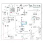
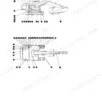
Yes, as separate full-size sheets in the ZIP, not buried as pages inside the book. You get the 3438-page repair manual plus three Electrical System schematic PDFs (KENR5118-03, UENR1753-04, KENR8666-07) and one Hydraulic System schematic sheet. Keeping them as their own files matters in practice: you can put the wiring sheet on one screen and the troubleshooting text on another, or print the schematic large enough that you can actually trace a circuit with a finger covered in grease. p. 1622
Reviews
There are no reviews yet.