
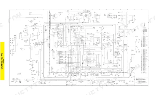
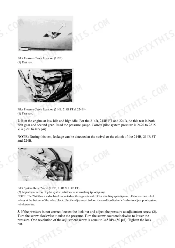
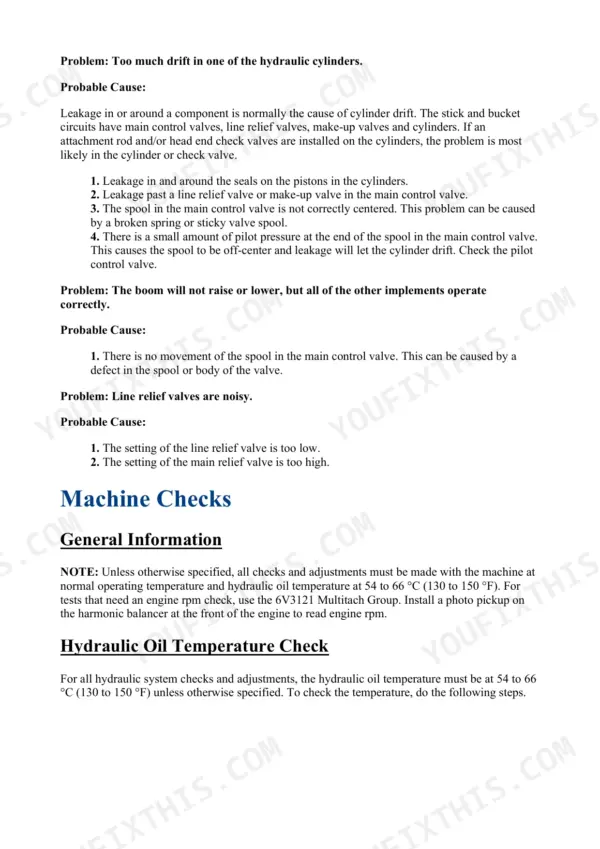
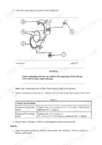
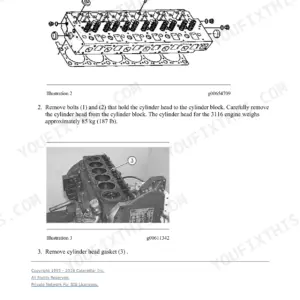
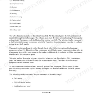
This is the full repair set for the Cat 214B and 214B FT wheel excavators, 1988 to 2000, covering the 3114/3116/3126 engines, hydraulics, power train and electrical. You get Testing and Adjusting with real numbers (pilot pressure, swing relief, pump cutoff), Disassembly and Assembly for the engine and vehicle systems, the 3116 supplement with the connecting rod torque procedure, plus MUI governor and 37-MT/41-MT/42-MT starting motor service. One honest note: about a quarter of the 3050 pages is bundled dealer software documentation (EquipmentManager and Product Link telematics manuals), not wrench material. The rest is the genuine shop content, including the electrical wiring schematic printed for the 214B, 214B FT and 224B.
What's Inside This Caterpillar 214B, 214BFT Repair Manual
| System | Pages | Key Topics |
|---|---|---|
| Air Inlet and Exhaust System | 1-53 | Turbocharger, Engine Pressure Group |
| Basic Engine | 54-443 | Crankshaft and Front Seal, Camshaft Bearing Tool Group, Journal Undersize Limits |
| Cooling System | 444-532 | Water Pump, Pressurizing Pump, O-Ring Seals |
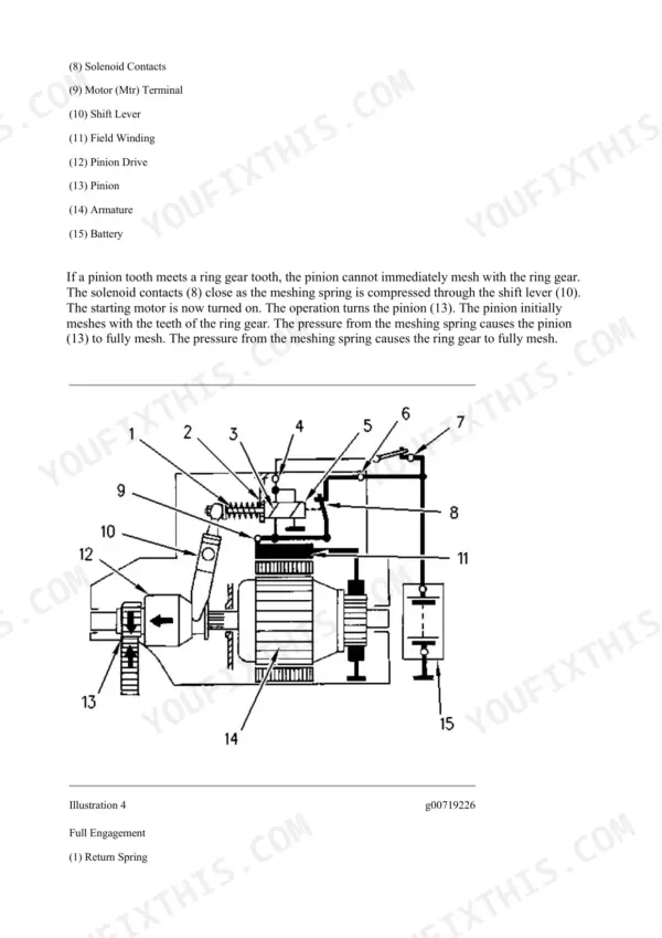
| Electrical and Starting System | 533-561 | Starting Motor Engagement (Partial, Blocked, Full), Electrical System General Information |
| EquipmentManager Dealer Software | 562-1016 | Status History Views, Maintenance Planner, Quote Requests, Dealer User Administration |
| Product Link Telematics Software | 1017-1387 | Product Link 121S/300, Product Link PL522/523, Connectors, Troubleshooting |
| Fuel Shutoff and Electrical Components | 1388-1507 | Energize-To-Shutoff (ETS) Latching Type, Energize-To-Run (ETR) Nonlatching Type |
| Engine Arrangement | 1508-1524 | Cylinder and Valve Location, Engine Speed Check |
| Frame and Body | 1525-1539 | Swing Gear and Bearing, Counterweight |
| Fuel System | 1540-2233 | Governor Repair Fixture, Shim Adjustment Tool, Servo Block, Governor Output Servo |
| Hydraulic System | 2234-2712 | Main Pump, Main Control Valve Bank, Shuttle Valve, Boom Cylinder, Swing Brake Valve |
| Implements | 2713-2727 | Stabilizer Cylinder, Axle Stabilizer Cylinder Group, Boom Removal and Installation |
| Lubrication System | 2728-2776 | |
| Operator Station | 2777-2795 | Heater Blower, Cab Removal and Installation, Steering Column Assembly |
| Power Train | 2796-2950 | Gear Tooth Contact Patterns Under Load and No Load, Travel Motor Brake Valve |
| Schematic Sheets | 2951-2977 | Electrical Schematic for the 214B, 214B FT and 224B, Hydraulic Circuit Sheet Printed for the 224B, Operator Station, Alternator, Indicators |
| Service Equipment and Supplies | 2978-2999 | Fuel Filters and Water Separator, Duo-Cone Seals |
| Torque Specifications | 3000-3047 | Standard Torque Tables, Thread Sizes, Torques for Mating with Ferrous Materials |
| Work Tools | 3048-3050 | Dozer Cylinder, Bucket Removal and Installation |
Quick Reference Specifications
| Specification | Value | Page |
|---|---|---|
| Pilot system pressure (214B, 214B FT & 224B) | 2470 to 2815 kPa (360 to 405 psi) | p. 2451 |
| Pilot relief valve adjustment sensitivity | 1 turn of adjustment screw = 345 kPa (50 psi) | p. 2451 |
| Swing relief pressure, with pilot pressure | 22 000 to 23 500 kPa (3200 to 3420 psi) | p. 2459 |
| Swing relief pressure, without pilot pressure (spring only) | 8000 kPa (1150 psi) | p. 2460 |
| Swing crossover relief valve, bench-test maximum (with pilot) | 22 750 ± 750 kPa (3310 ± 110 psi) | p. 2528 |
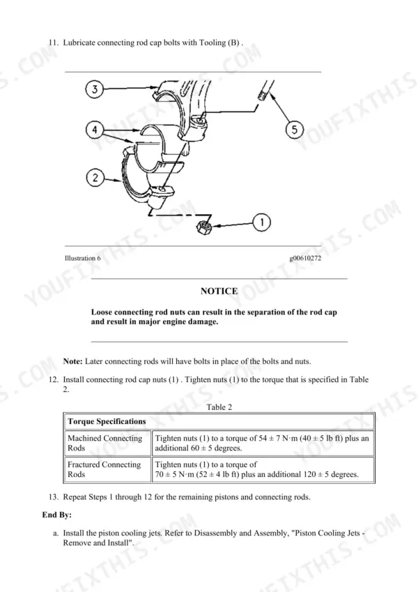
| Connecting rod cap nut torque, machined rods | 54 ± 7 N·m (40 ± 5 lb ft) + additional 60 ± 5 degrees | p. 389 |
| Connecting rod cap nut torque, fractured rods | 70 ± 5 N·m (52 ± 4 lb ft) + additional 120 ± 5 degrees | p. 389 |
| Auxiliary (pilot) pump priority valve torque (213B, 214B & 214B FT) | 220 N·m (160 lb ft) | p. 2590 |
| Auxiliary pump flow rate to cooler motor | 45 liter/min (12 U.S. gpm) | p. 2590 |
| Auxiliary pump flow rate to pilot oil system | 15 liter/min (4.0 U.S. gpm) | p. 2590 |
| Aux pump circuit main relief valve setting | 10 000 kPa (1450 psi) | p. 2592 |
| Wheel drive motor line relief valve setting (214B, 214B FT & 224B) | 42 000 kPa (6100 psi) | p. 2576 |
| Wheel drive motor line relief valve torque | 120 N·m (90 lb ft) | p. 2576 |
| Steering valve bolt torque (214B, 214B FT & 224B) | 32 ± 3 N·m (24 ± 2 lb ft) | p. 2634 |
| Steering valve secondary pressure relief valve setting | 22 000 kPa (3200 psi) | p. 2635 |
| Steering valve primary pressure relief valve setting | 15 000 ± 500 kPa (2200 ± 100 psi) | p. 2635 |
| High pressure cutoff valve setting | 29 900 to 32 000 kPa (4350 to 4650 psi) | p. 2670 |
| High pressure relief bias setting | 6050 ± 50 kPa (875 ± 88 psi) | p. 2670 |
| Maximum pump pressure | 38 100 kPa (5500 psi) | p. 2670 |
Caterpillar 214B, 214BFT Common Problems This Manual Covers
Machine bogs or loses pulling power under load but responds normally unloaded
Classic sign of internal pump or motor wear. Run the pressure checks in Hydraulic Testing and Adjusting against the high pressure cutoff spec of 29 900 to 32 000 kPa on page 2670. Low readings under load point to worn piston shoes or barrel, not a valve adjustment.
Manual Section: Hydraulic Testing and Adjusting p. 2670Boom or stabilizer cylinders drift down, or a relief valve squeals under pressure
Hydraulic Testing and Adjusting has dedicated troubleshooting for cylinder drift and noisy relief valves. It shows you how to isolate whether oil is bypassing the cylinder piston seals or leaking through a control valve, and how to reseat or adjust a chattering relief instead of guessing and swapping parts.
Manual Section: Hydraulic Testing and Adjusting p. 2434Engine rebuild on the 3116 and unsure of the rod cap procedure
The 3116 Diesel Engine Supplement for 213B and 214B excavators gives the machine-specific assembly steps and the two rod torque tables on page 389: 54 ± 7 N·m plus 60 degrees for machined rods, 70 ± 5 N·m plus 120 degrees for fractured rods. Identify your rod type first.
Manual Section: 3116 Diesel Engine Supplement for 213B and 214B Excavators p. 389Slow cranking or starter that drags and clicks on cold mornings
The Engine Governors and Starting Motors section covers teardown, testing and rebuild of the 37-MT, 41-MT and 42-MT starting motors used on these machines. It walks through brush, armature and solenoid checks so you can rebuild the unit on the bench instead of paying exchange price for a new starter.
Manual Section: Engine Governors and Starting Motors p. 541Frequently Asked Questions
My 214B travels fine empty but bogs down and loses pulling power under load. Will this manual help me find out why?
Yes, and that symptom is usually internal wear in the hydrostatic pump or motor, worn piston shoes or a scored barrel. The Hydraulic Testing and Adjusting section walks you through the pressure checks that separate a tired pump from a relief valve set low. The book gives you the numbers to test against: high pressure cutoff at 29 900 to 32 000 kPa (4350 to 4650 psi) and maximum pump pressure of 38 100 kPa (5500 psi), both on page 2670. If the machine cannot build those pressures under load, you know where the money is going. p. 2670
Does it have the connecting rod torque for the 3116? I have heard there are two different specs.
It does, on page 389, and yes there are two because Cat used two rod types. Machined rods take 54 ± 7 N·m (40 ± 5 lb ft) plus an additional 60 ± 5 degrees. Fractured rods take 70 ± 5 N·m (52 ± 4 lb ft) plus an additional 120 ± 5 degrees. Use the wrong one and you will spin a bearing. The 3116 Diesel Engine Supplement for the 213B and 214B covers the machine-specific teardown and rebuild around it. p. 389
Is there a hydraulic schematic for the 214B in this book?
The only printed hydraulic circuit diagram (pages 2953 to 2954) is labeled for the 224B, not the 214B or 214B FT. The 214B is still fully covered for actual work through the Hydraulic System Specifications, Hydraulic System Operation and Hydraulic Testing and Adjusting sections, which name the 214B and 214B FT directly, there is just no dedicated 214B schematic sheet. The electrical wiring schematic on page 2952 is printed for the 214B, 214B FT and 224B together. p. 2953
Do I need a laptop or code reader to troubleshoot this machine?
No. The machine itself is fully mechanical, MUI fuel system, no ECM, no fault codes. Troubleshooting is done with pressure gauges, a tach and your eyes, exactly how the Testing and Adjusting sections are written. The book does bundle Product Link telematics and EquipmentManager dealer software manuals, but that is dealer-side fleet software documentation, not something you need to fix the excavator. p. 2431
What hydraulic pressure specs are actually in here for setting up the system?
The Hydraulic System Specifications section covers the 213B, 214B, 214B FT and 224B. Examples with page numbers: pilot system pressure is 2470 to 2815 kPa (360 to 405 psi) on page 2451, swing relief with pilot pressure is 22 000 to 23 500 kPa (3200 to 3420 psi) on page 2459, and the high pressure cutoff and maximum pump figures are on page 2670. Steering, pump relief and wheel drive motor specs are in the same section. p. 2451

![Caterpillar 311 repair manual - Electrical & Starting System, [Elec #12-1] Wiper System Problem](https://youfixthis.com/wp-content/uploads/2019/12/caterpillar-311-repair-manual-9lj00262-up-excavator-page-575-150x150.webp)
Reviews
There are no reviews yet.