
This is a 5,999-page Caterpillar repair manual set for the M320 wheeled excavator, serial prefixes 9PS and 6WL, powered by the Caterpillar 3116 engine. It is a Caterpillar SIS export of several factory books interleaved, and because the M320 runs on axles rather than tracks it covers the transmission, differentials, wheel brakes, oscillating axle, dozer blade and stabilizers alongside the digging systems.
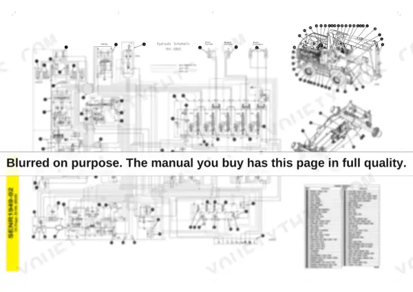
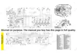
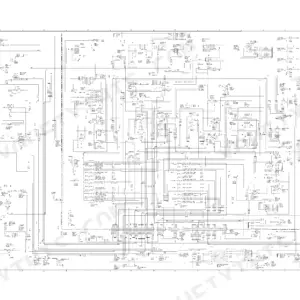
Two fold-out schematics are rendered as full sheets. On page 5805 sits the M320 hydraulic schematic, SENR1949-02, with a standard components table numbering 67 items, from the main pump, swing motor and swing charge pump to the wheel brake valve, travel brake valve, oscillating axle accumulator, steering flow control valve, creeper speed solenoid valve and pilot manifold, plus two machine callout illustrations that locate every numbered item on the excavator and on the carrier. On page 5800 is the M318 and M320 electrical schematic, RENR4035, whose title block reads M318 8SS470-UP and M320 9PS287-UP; it carries four reference tables, including resistance values in ohms for resistors, senders and solenoids and the actuate and deactivate pressures for every off-machine switch.
Measured page by page, the set breaks down as 1,364 pages of generic 3114/3116/3126 engine books, 1,330 pages of M320 machine systems, 738 pages of Product Link and EquipmentManager telematics, 706 pages of M318 and M320 power train, 604 pages of machine hydraulics, 311 pages of air conditioning and 107 pages on the starting motor.
What's Inside This Caterpillar M320 Repair Manual
| System | Pages | Key Topics |
|---|---|---|
| Air Inlet & Exhaust System | 1-72 | Turbocharger - Inspect, Inlet Manifold Pressure - Test, Aftercooler and Exhaust Manifold Service |
| Basic Engine - Testing & Rebuild | 73-474 | Finding Top Center Position for No. 1 Piston, Gear Group (Front) - Time, Engine Crankcase Pressure (Blowby) - Test, Compression - Test, Bearing, Piston and Cylinder Block Inspection |
| Cooling System | 475-600 | Cooling System - Check - Overheating, Water Temperature Regulator - Test, Water Pump and Oil Cooler Service |
| Electrical & Machine Control - Systems Operation | 601-1230 | Electrical System Component Description, Fuel Shutoff Solenoid, Pressure Switch (Refrigerant), Normal Operation of the Machine Circuits, Product Link Modules |
| Electrical - Testing & Adjusting | 1231-1401 | Battery - Test, Charging System - Test, Electric Starting System - Test, Pinion Clearance - Adjust, Starting Motor Solenoid - Test, No Load - Test |
| Electrical - Troubleshooting | 1402-1562 | Starting Motor Does Not Turn or Turns Slowly, Engine Does Not Crank with the Pinion Engaging the Ring Gear, Electronic Service Tool Does Not Communicate with ECM, Service Tools |
| Electrical - Specifications, Disassembly & Assembly | 1563-1757 | Alternator and Regulator - Remove and Install, V-Belts (Alternator and Fan), Ether Starting Aid Valve Assembly and Cylinder, Jacket Water Heater |
| Engine Arrangement, Frame & Body | 1758-1884 | Engine Speed - Check, Engine Performance - Test, System Pressure - Release, Frame and Body Panels |
| Fuel System - Operation, Testing & Adjusting | 1885-2040 | Dashpot (Types I, Iii, Iv, V, VI and VII), Dual Horsepower (Types VI and VII), Fuel Ratio Control by Governor Type, Governor Circuits |
| Fuel System - Specifications, Disassembly & Assembly | 2041-2634 | Fuel Injection Control Linkage - Remove and Install, Fuel Filter Base, Fuel Filter (Primary), Governor Overhaul by Type, Injection Pump Service |
| Hydraulic System - Systems Operation | 2635-2864 | Main Hydraulic System, Pilot Hydraulic System, Hydraulic Filter (Pilot), Pilot Valve (Pilot Manifold), Relief Valve (Pilot) |
| Hydraulic System - Testing & Adjusting | 2865-3072 | Proportional Reducing Valve - Test, Visual Inspection, Hydraulic System Pressure - Release, Main Hydraulic Pump Air - Purge, Swing Pump Air - Purge |
| Hydraulic - Accumulators, Cylinders, Cooler & Solenoids | 3073-3650 | Wheel Brake Accumulators, Pilot Accumulator, Solenoid Valves for Travel Activation, Implement Activation, Swing Brake and Creeper Speed, Radiator and Hydraulic Oil Cooler, Stick and Bucket Cylinder Removal, Swing Drive - Remove |
| Hydraulic - Pumps, Motors, Steering & Control Valves | 3651-4228 | Swing Motor, Brake/Pilot Steering/Cooling Pump, Swing Charge Pump, Main Hydraulic Pump and Pump Drive Coupling, Swing and Main Pump Pressure Reducing Valves, Steering Cylinder, Travel Brake Valve - Remove, Stick Drift Reduction Valve |
| Implements - Boom, Stick & Attachment Control | 4229-4389 | Control Valve (VA Boom Lowering), Boom - Remove, Boom Bearings and Seals, Pilot Control Valve (Fore Boom) |
| Lubrication System & Machine Arrangement | 4390-4461 | Engine Oil Pressure - Test, Excessive Engine Oil Consumption - Inspect, Increased Engine Oil Temperature - Inspect |
| Air Conditioning - Systems Operation | 4462-4586 | Air Conditioning System Schematic, Accumulator (Air Conditioner), Refrigerant Compressor, Refrigerant Relief Valve |
| Air Conditioning - Testing, Adjusting & Troubleshooting | 4587-4802 | Refrigerant Recovery, Manifold Gauge Set (Refrigerant) - Install, Refrigerant System - Evacuate, Refrigerant Compressor Oil - Check, General Troubleshooting Information |
| Air Conditioning - Disassembly, Assembly & Capacities | 4803-5060 | Motor (Air Conditioning Blower), Pressure Switch (Refrigerant Pressure Cutoff), System Capacities for Refrigerant, M312 to M320, Compressor Removal and Refitting |
| Power Train - Systems Operation | 5061-5102 | Axle (Front and Rear), Differentials, Transmission Downshift Inhibitor, Control Valve (Oscillating Axle and Operating Brake), Accumulator (Brake Control Valve) |
| Power Train - Axles, Final Drives & Transmission Overhaul | 5103-5797 | Final Drive Carriers, Hubs and Brakes - Disassemble, Front and Rear Axle, Hubs and Brakes - Assemble, Housing and Bearings (Steer Axle) - Remove, Gearbox Strip and Rebuild |
| Fold-Out Schematics & Graphic Symbols | 5798-5850 | M320 Hydraulic System Schematic with Its Standard Component Table, M318 and M320 Excavators Electrical System Schematic, Auxiliary Circuit, General Priority Valve and Generator Priority Attachment Sheets, Low Pressure Function Sheet, Fluid Power Graphic Symbols, Machine Harness Connector and Component Locations |
| Service Equipment, Supplies & Steering | 5851-5907 | Cab Pressurization and Filtration System, Required Tools, Heating and Air Conditioning Service Publications, Steering System Service |
| Work Tools, Stabilizers, Dozer Blade & Torque Specifications | 5908-5999 | Stabilizer Arm Assemblies, Dozer Blade Linkage, Stabilizer and Blade System Operation, Standard Torque Values |
Caterpillar M320 Common Problems This Manual Covers
The whole machine digs slow. Boom and bucket feel weak, and it gets worse once the oil warms up.
Start with Hydraulic System - Testing & Adjusting, pages 2865 to 3072: it opens with a visual inspection procedure, then covers the proportional reducing valve test and air purging for the main hydraulic pump and the swing pump. Read the main and pilot circuit descriptions in Hydraulic System - Systems Operation, pages 2635 to 2864, and trace the circuit on the fold-out hydraulic schematic at page 5805, which names all 67 standard components and shows where each one sits on the machine.
Manual Section: Hydraulic System - Testing & AdjustingIt will not hold on a slope. The wheel brakes feel weak and the machine creeps when parked on a grade.
Start with the brake circuit: the wheel brake accumulators are in Hydraulic - Accumulators, Cylinders, Cooler & Solenoids, pages 3073 to 3650, and Power Train - Systems Operation, pages 5061 to 5102, describes the brake control valve accumulator and the oscillating axle and operating brake control valve. For the brakes themselves, Power Train - Axles, Final Drives & Transmission Overhaul, pages 5103 to 5797, strips and rebuilds the final drive carriers, hubs and brakes on the front and rear axles.
Manual Section: Power Train - Axles, Final Drives & Transmission OverhaulThe steering has gone heavy and jerky when roading the machine.
Hydraulic - Pumps, Motors, Steering & Control Valves, pages 3651 to 4228, covers the steering cylinder and the brake/pilot steering/cooling pump that feeds the circuit. Steering system service also appears in Service Equipment, Supplies & Steering, pages 5851 to 5907. On the hydraulic schematic at page 5805 the steering valve and the steering flow control valve are numbered components, so you can trace the circuit before pulling anything apart.
Manual Section: Hydraulic - Pumps, Motors, Steering & Control ValvesSwing is slow and weak in one direction, and the upper structure hesitates before it starts to move.
Hydraulic System - Testing & Adjusting, pages 2865 to 3072, includes the swing pump air purge. The swing motor, the swing charge pump and the swing pump pressure reducing valve are handled in Hydraulic - Pumps, Motors, Steering & Control Valves, pages 3651 to 4228, and the swing brake solenoid valve and Swing Drive - Remove sit in Hydraulic - Accumulators, Cylinders, Cooler & Solenoids, pages 3073 to 3650.
Manual Section: Hydraulic System - Testing & AdjustingFrequently Asked Questions
Is this the wheeled M320, or a tracked 320?
The wheeled machine. The M320 runs on axles, not tracks: it has front and rear axles with differentials, a transmission with a downshift inhibitor, wheel brakes, an oscillating front axle and optional dozer blade and stabilizers. The power train book inside is titled 'M318 and M320 Excavators Power Train' and strips and rebuilds the final drive carriers, hubs and brakes on both axles. If you own a tracked 320, this is not your manual.
How do I know the electrical schematic matches my serial number?
The title block on the sheet at page 5800 reads M318 8SS470-UP and M320 9PS287-UP, so the electrical schematic is drawn for M320 machines from serial 9PS287 up. The manual set as a whole is for serial prefixes 9PS and 6WL. Check the prefix and number on your machine plate before buying.
Are all 5,999 pages about the M320 itself?
No, and the split was measured page by page from the media numbers in the headers. 1,330 pages are the M320 machine systems book, 706 the M318 and M320 power train book and 604 the machine hydraulic books. 1,364 pages are generic 3114/3116/3126 engine books that Caterpillar shares across products, a substantial block of the set cover Product Link and EquipmentManager telematics, 311 cover air conditioning and 107 the starting motor. If your machine has no Product Link hardware, you can skip that block entirely.
Does it cover rebuilding the 3116 engine?
Yes. Basic Engine - Testing & Rebuild runs from page 73 to 474 and includes finding top center for the No. 1 piston, front gear group timing, crankcase pressure (blowby) and compression tests, and bearing, piston and cylinder block inspection. Fuel system work, including governor overhaul by type and injection pump service, runs from page 1885 to 2634, and the cooling system section on pages 475 to 600 covers overheating checks, the water temperature regulator and the water pump. p. 73
My cab air conditioning stopped cooling. Is that in here?
Yes. Air conditioning runs from page 4462 to 5060, 311 pages measured, split into systems operation, testing and troubleshooting, and disassembly and assembly. It covers the refrigerant compressor, the refrigerant pressure cutoff switch, the blower motor, refrigerant recovery, system evacuation and compressor oil checks, and includes the all-products R134a book.
![Caterpillar 311 repair manual - Electrical & Starting System, [Elec #12-1] Wiper System Problem](https://youfixthis.com/wp-content/uploads/2019/12/caterpillar-311-repair-manual-9lj00262-up-excavator-page-575-150x150.webp)


Reviews
There are no reviews yet.