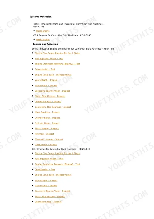
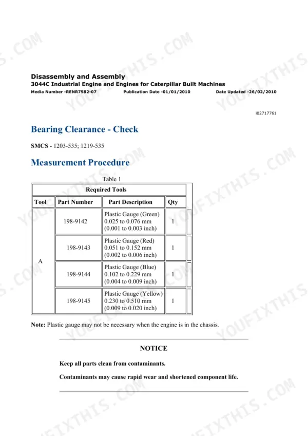
This is the full Cat SIS repair bundle for the 236B, 246B, 252B, and 262B skid steers built 2004 to 2008, all running the 3044C (C3.4) diesel. You get Testing and Adjusting, Systems Operation, Disassembly and Assembly, plus the actual hydraulic and electrical schematic sheets, over 4,400 pages total. This is the material a Cat dealer tech pulls up before touching your machine: real pressure specs for the main relief (23000 kPa), line reliefs, pilot circuit, and charge pump, wiring harness open and short circuit test procedures, and step-by-step teardown for everything from the cylinder head to the final drives. If you own one of these B-series loaders out of warranty, this pays for itself the first time you skip a shop visit.
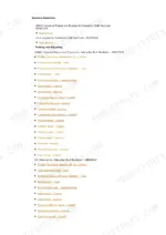
What's Inside This Caterpillar 236B-262B Repair Manual
| System | Pages | Key Topics |
|---|---|---|
| Schematics | 52-150 | Hydraulic and Electrical System Schematic Sheets, Fluid Power and Electrical Graphic Symbols |
| Air Inlet and Exhaust System | 151-242 | Air Cleaner, Turbocharger, Exhaust, Muffler |
| Basic Engine | 243-975 | Cylinder Head, Pistons, Crankshaft, C3.4/3044C Engine |
| Cooling System | 976-1173 | Water Pump, Thermostat, Radiator, Cooling Tests |
| Electrical and Starting System | 1174-2295 | Alternator, Starter, Batteries, Wiring Harness open/short Circuit Tests, System Schematics, Component Locations |
| Engine Arrangement | 2296-2458 | 3044C/C3.4 Engine Arrangement and Specifications |
| Frame and Body | 2459-2497 | Frame, Guards, Covers |
| Fuel System | 2498-2684 | Fuel Injection, Fuel System Pressure, Priming |
| Hydraulic System | 2685-3266 | Main and Line Relief Valve Pressures, Pilot System, Accumulator, Charge Pump, Hydraulic Tests |
| Implements | 3267-3292 | Loader Linkage, Lift and Tilt Cylinders |
| Lubrication System | 3293-3402 | Oil Pump, Engine Oil Relief Valve, Lubrication |
| Machine Arrangement | 3403-3414 | Overall Machine Arrangement |
| Operator Station | 3415-3929 | Cab, Controls, Seat, HVAC |
| Power Train | 3930-4372 | Hydrostatic Drive, Motors, Final Drives, Parking Brake |
| Service Equipment and Supplies | 4373-4395 | Tooling, Fluids, Supplies |
| Torque Specifications | 4396-4443 | Standard Bolt Torque Charts |
| Work Tools | 4444-4453 | Work Tool Attachments |
Quick Reference Specifications
| Specification | Value | Page |
|---|---|---|
| 236B/246B/252B/262B | ||
| Main Relief Valve Pressure | 23000 ± 700 kPa (3336 ± 102 psi) | p. 2857 |
| Line Relief Valve Pressure - Lift Cylinder Head Raise position | 27600 ± 700 kPa (4003 ± 102 psi) | p. 2868 |
| Line Relief Valve Pressure - Tilt Cylinder Head Tilt Forward position | 24500 ± 700 kPa (3554 ± 102 psi) | p. 2868 |
| Line Relief Valve Pressure - Tilt Cylinder Rod Tilt Back position | 27600 ± 700 kPa (4003 ± 102 psi) | p. 2868 |
| Line Relief Valve Pressure - Auxiliary Circuit | 24500 ± 700 kPa (3554 ± 102 psi) | p. 2868 |
| Charge Pump Minimum Flow | 32 L/min (8.45 US gpm) | p. 2890 |
| All models (Type 1 relief valve) | ||
| Main Relief Valve Locknut Torque | 24 ± 3 N·m (18 ± 2 lb ft) | p. 2868 |
| Main Relief Valve Cap Torque | 24 ± 3 N·m (18 ± 2 lb ft) | p. 2868 |
| All models (at 2300 ± 25 RPM) | ||
| Pilot Pressure (Engine RPM) | 3225 ± 200 kPa (468 ± 29 psi) | p. 2873 |
| All models | ||
| Accumulator Charge Pressure | 900 ± 100 kPa (130 ± 15 psi) | p. 2873 |
| Pilot System Pressure - Charge Pressure (Low Idle) | 3100 ± 200 kPa (450 ± 29 psi) | p. 2884 |
| Pilot System Pressure - Pilot Pressure for the Work Tool (Low Idle) | 3100 ± 200 kPa (450 ± 29 psi) | p. 2884 |
| Pilot System Pressure - Charge Pressure (2300 ± 25 RPM) | 3225 ± 200 kPa (468 ± 29 psi) | p. 2884 |
| Pilot System Pressure - Pilot Pressure for the Work Tool (2300 ± 25 RPM) | 3225 ± 200 kPa (468 ± 29 psi) | p. 2884 |
| Brake Pressure (Initial) | less than 300 kPa (44 psi) | p. 2886 |
| Brake Line Pressure (Parking Brake Disengaged) | 3100 ± 200 kPa (450 ± 29 psi) | p. 2886 |
| Charge Pump Outlet Pressure | 18000 ± 1000 kPa (2611 ± 145 psi) | p. 2890 |
| Charge Pump Test Engine Speed | 2000 ± 10 RPM | p. 2890 |
| Charge Pump Test Oil Temperature | 45° ± 5°C (113° ± 9°F) | p. 2890 |
| Work Tool Pump Test Oil Temperature | 50° ± 10°C (122° ± 18°F) | p. 2892 |
| Work Tool Pump Outlet Pressure | 18000 ± 1000 kPa (2611 ± 145 psi) | p. 2892 |
| Work Tool Pump Test Engine Speed | 2000 ± 10 RPM | p. 2892 |
Caterpillar 236B-262B Common Problems This Manual Covers
Loader loses hydraulic pressure, lift arms drift down, or movement gets erratic under load.
Run the pressure tests in the Hydraulic System section: check main relief at 23000 ± 700 kPa, then line reliefs and pilot pressure at 3225 ± 200 kPa. The procedures isolate whether the fault is a relief valve, the work tool pump, or leaking cylinder seals before you order parts.
Manual Section: Hydraulic System (pages 2685-3266)Machine loses traction, drives weak on one side, or the hydrostatic drive fails outright.
Start with the charge pump test in the Power Train section: 18000 ± 1000 kPa outlet and 32 L/min minimum flow at 2000 RPM. Low charge pressure starves the drive loop. The section also covers motor and final drive teardown, chains, sprockets, and parking brake pressure checks.
Manual Section: Power Train (pages 3930-4372)Engine overheats, loses power, or the 3044C needs a cylinder head pulled after a head gasket failure.
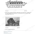
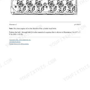
The Basic Engine section gives the full disassembly and assembly sequence for the cylinder head, pistons, and crankshaft on the 3044C/C3.4. Pair it with the Cooling System section's water pump, thermostat, and cooling tests to confirm what cooked the engine before you rebuild it.
Manual Section: Basic Engine (pages 243-975)Starter clicks, battery drains, or an intermittent wiring fault keeps shutting things down.
The Electrical and Starting System section has component locations, system schematics, and structured open circuit and short circuit tests for the wiring harness. You follow the test tree with a multimeter instead of guessing, covering alternator, starter, and battery checks along the way.
Manual Section: Electrical And Starting System (pages 1174-2295)Frequently Asked Questions
Does this manual give the actual hydraulic pressure specs, or just tell me to see the dealer?
Real numbers, with tolerances. Main relief valve is 23000 ± 700 kPa (3336 ± 102 psi). Line reliefs run 24500 to 27600 kPa depending on circuit: lift cylinder head end in RAISE is 27600 ± 700 kPa (4003 psi), tilt forward is 24500 ± 700 kPa (3554 psi), auxiliary circuit is 24500 kPa. Pilot pressure is 3225 ± 200 kPa at 2300 RPM, accumulator charge is 900 ± 100 kPa. The Hydraulic System section walks you through where to tee in the gauge and how to run each test.
My loader is weak or jerky on lift and tilt. Will this help me find the cause?
Yes, that is exactly what the Testing and Adjusting content is for. You start with the main and line relief pressure tests, then the pilot system test, then the work tool pump outlet test (18000 ± 1000 kPa at 2000 RPM with oil at 50°C). Each test either passes or points you to the next component, so you find out whether it is a relief valve set low, a tired pump, or a pilot problem before you buy anything. Beats swapping a pump on a guess.
Does it cover the drive system and parking brake?
The Power Train section (over 400 pages) covers the hydrostatic drive pumps and motors, final drives with the chains and sprockets, and the parking brake. It includes the charge pump test: 18000 ± 1000 kPa outlet pressure and a minimum flow of 32 L/min at 2000 RPM, which is the first check when the machine loses traction or creeps. Brake line pressure with the parking brake disengaged should read 3100 ± 200 kPa; the procedure to verify that is included.
Are the electrical schematics included? I have a wiring gremlin.
Yes. There is a dedicated Schematics section with the full hydraulic and electrical schematic sheets plus a symbol key, and the Electrical and Starting System section (over 1,100 pages) covers alternator, starter, batteries, component locations, and step-by-step wiring harness open circuit and short circuit tests with a multimeter. These are 2004 to 2008 machines, so most electrical faults get chased with the schematic and a meter, and this gives you both the drawings and the procedure.
I need torque specs. Are they in here?
There is a standard bolt torque chart section, and specific fasteners get their values in the assembly procedures where they belong. For example, the Type 1 main relief valve locknut and cap both torque to 24 ± 3 N·m (18 ± 2 lb ft), which matters because that valve sets your 23000 kPa system pressure. Engine fasteners like head bolts and flywheel housing bolts are covered in their own Basic Engine assembly steps rather than a single lookup table.