

A 4,010 page Caterpillar SIS repair manual export for the 216B, 226B, 232B and 242B Skid Steer Loaders, serial prefixes RLL, MJH, SCH and BXM, several manuals interleaved into one file. The first number a buyer needs is the main relief split: machines RLL1-6799 and SCH1-2474 are set to 21400 +/- 700 kPa (3104 +/- 102 psi), while MJH1-Up, SCH2475-Up and BXM1-Up take 23000 +/- 700 kPa (3336 +/- 102 psi), with the test and adjust procedure on page 2390.
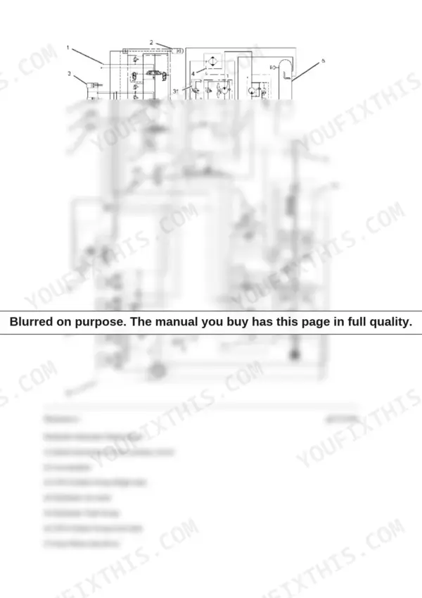
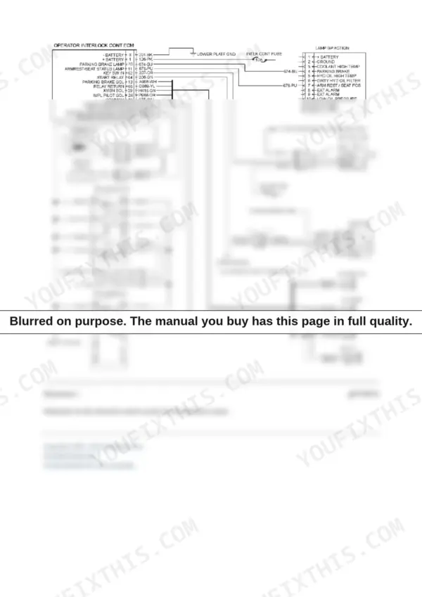
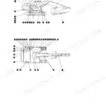
The machine-specific books are RENR4894 through RENR4898, the power train and machine systems volumes, and the schematics are here in full. Page 2196 carries the single-speed hydraulic schematic with a 31-item key that runs from the auxiliary quick disconnects, accumulator and tilt cylinders through the oil cooler, tank group, fan drive gear motor, lift cylinders, work tool control valve and return manifold to the hydrostatic piston pumps and motors. Page 1296 carries the interlock wiring schematic drawn pin by pin to the operator interlock ECM, with wire numbers, colour codes and the armrest, seat, implement lockout and park brake switches.
Know what the total is made of: 1,229 pages are generic Cat engine books for the 3024C and C2.2, 731 pages are Product Link telematics, 364 pages are B2-series books for a later machine, 291 pages are air conditioning and 128 are the Machine Security System. It is a bundle, and that is stated plainly here.
Other edition of this manual
What's Inside This Caterpillar 216B, 226B, 232B, 242B Repair Manual
| System | Pages | Key Topics |
|---|---|---|
| Air Inlet & Exhaust System | 1-27 | Exhaust Temperature - Test, Turbocharger - Remove and Install, Exhaust Manifold - Remove and Install |
| Basic Engine - Operation & Testing | 28-135 | Finding Top Center Position for No. 1 Piston, Compression - Test, Engine Crankcase Pressure (Blowby) - Test, Engine Valve Lash - Inspect/Adjust, Valve Depth and Valve Guide - Inspect, Cylinder Head and Cylinder Block - Inspect |
| Basic Engine - Specifications, Disassembly & Assembly | 136-522 | Camshaft - Remove, Install, Disassemble and Assemble, Belt Tension Chart, Crankshaft Front and Rear Seals, Crankshaft Main Bearings - Remove and Install, Connecting Rod Bearing Journal, Main Bearing Journal |
| Cooling System | 523-677 | Cooling System - Check - Overheating, Water Temperature Regulator - Test, Water Pump - Inspect, Radiator and Hydraulic Oil Cooler, Gear Motor (Fan) and Fan Drive, Disconnecting Snap to Connect Fittings |
| Electrical & Interlock System - Systems Operation | 678-744 | Engine Start Interlock, Hydrostatic System Interlock and Parking Brake Interlock, Work Tool Interlock, Electronic Control Module (ECM) and Cat Data Link, Solenoid Valves and Relays, Pressure Switch (Refrigerant) |
| Product Link & EquipmentManager (Telematics Portal) | 745-1184 | Product Link Installation, Setup Subscriptions and Manage Users, Manage Equipment Groups and Hardware, Manage Event Tracking and Upload Data, Time Fence and Geographic Fence, Preferences and Preference Detail |
| Machine Security System | 1185-1281 | Operation of Status Indicator, Key Information, Scheduled Access - Security System Bypass Times, Protected Functions, Service Operation Using Service Tool, Installation Parameters Configure |
| Electrical - Testing & Adjusting | 1282-1446 | Wiring Harness (Open and Short Circuit) - Test, Alternator - Test, Battery - Test, Charging System - Test, Glow Plugs - Test, Electronic Control Module (ECM) - Flash Program and Replace, Product Identification Number - Program |
| Troubleshooting - Diagnostic Codes & Connector Locations | 1447-1772 | Electrical Component and Connector Locations, Diagnostic Capabilities, Diagnostic Code List, MID 106 CID/FMI Code Entries, Service Tools |
| Electrical - Specifications, Disassembly & Assembly | 1773-1860 | Alternator - Remove and Install, 55, 65 and 85 Amp, Battery and Battery Cable - Separate and Connect, Glow Plugs - Remove and Install, Electric Starting Motor - Remove and Install, Coolant Temperature Switch, Engine Oil Pressure Switch |
| Engine Arrangement - Removal & Installation | 1861-1972 | Engine Design, Engine Speed - Check, Engine - Remove, Engine - Install |
| Frame & Body | 1973-2003 | Machine Frame and Mounting, Engine Enclosure - Remove and Install, Lift Arm Cylinder and Mounting |
| Fuel System | 2004-2194 | Fuel Injection Nozzle - Test, Fuel Injection Timing - Check, Air in Fuel - Test, Fuel System Pressure - Test, Governor - Adjust, Fuel Priming Pump and Primary Filter (Water Separator) |
| Hydraulic System - Systems Operation | 2195-2364 | Pilot Hydraulic System, Pilot Valve (Joystick), Work Tool Hydraulic System, Control Valve (Work Tool), Control Manifold and Solenoid (Work Tool Positioner) |
| Hydraulic System - Testing, Adjusting & Troubleshooting | 2365-2516 | Main Relief Valve - Test and Adjust, Line Relief Valve - Test and Adjust, Pilot System Pressure - Test, Pump Flow - Test, Accumulator (Pilot) - Test and Charge, Hydraulic Oil Contamination - Test |
| Hydraulic System - Specifications, Disassembly & Assembly | 2517-2827 | Lift Cylinder - Remove and Install, Tilt Cylinder - Remove and Install, Coupler Cylinder - Remove and Install, Accumulator - Remove and Install, Radiator and Hydraulic Oil Cooler - Remove and Install, Hydraulic System Pressure - Release |
| Implements & Lubrication System | 2828-2961 | Engine Oil Pressure - Test, Engine Oil Pump - Inspect, Excessive Engine Oil Consumption - Inspect, Crankcase Breather - Naturally Aspirated and Turbocharged, Engine Oil Relief Valve - Remove and Install, Engine Oil Lines |
| Air Conditioning - Service Intervals | 2962-2973 | Condenser, Evaporator and Heater Coil Checks, Blowers and Fans, Compressor Drive Belt Wear and Damage |
| Operator Station & Air Conditioning - Systems Operation | 2974-3172 | Switches, Indicators and Sensors, Identifying the Refrigerant, Refrigerant Expansion Valve System, Refrigerant Orifice Tube System, Refrigerant Receiver-Dryer, In-Line Refrigerant Dryer |
| Operator Station - Troubleshooting by Code | 3173-3341 | Switch (Two Speed), Switch (Hydraulic Lockout), Switch (Armrest) and Switch (Seat), Switch (Parking Brake), Switch (Interlock Override), CID and FMI Entries for Each Switch Circuit |
| Air Conditioning & Heating - Disassembly, Assembly & Capacities | 3342-3605 | Air Conditioner and Heater - Remove, Disassemble, Assemble and Install, Refrigerant Compressor and Support Housing, Refrigerant Accumulator, Solenoid Valve (Compressor Motor), Gear Motor - Disassemble and Assemble, System Capacities for Refrigerant |
| Power Train - Hydrostatic System | 3606-3979 | Piston Pump (Hydrostatic), Piston Motor (Hydrostatic), Tandem Drive and Axle, Hydrostatic System - Flush and Fill, Hydrostatic System - Test and Adjust, Operational Checks and Troubleshooting Worksheets |
| Cab Filtration & Air Conditioning Service Reference | 3980-4010 | Cab Pressurization and Filtration System, Cab Air Filters, Manifold Gauge Set (Refrigerant) - Install and Remove, Heating and Air Conditioning Service Publications |
Quick Reference Specifications
| Specification | Value | Page |
|---|---|---|
| Hydraulic system | ||
| Main relief, RLL1-6799 and SCH1-2474 | 21400 +/- 700 kPa (3104 +/- 102 psi) | p. 2390 |
| Main relief, MJH1-Up, SCH2475-Up, BXM1-Up | 23000 +/- 700 kPa (3336 +/- 102 psi) | p. 2390 |
| Lift circuit | ||
| Line relief, lift cylinder head in the Raise position | 27600 +/- 700 kPa (4003 +/- 102 psi) | p. 2400 |
| Tilt circuit | ||
| Line relief, tilt cylinder head in the Tilt Forward position | 24500 +/- 700 kPa (3554 +/- 102 psi) | p. 2400 |
| Auxiliary circuit | ||
| Line relief, auxiliary circuit | 24500 +/- 700 kPa (3554 +/- 102 psi) | p. 2400 |
| Pilot circuit | ||
| Pilot pressure at 2550 +/- 25 rpm | 3225 +/- 200 kPa (468 +/- 29 psi) | p. 2405 |
| Pilot accumulator check pressure | 900 +/- 100 kPa (130 +/- 15 psi) | p. 2409 |
| Hydrostatic system | ||
| Hydrostatic MB pressure, pumps 1 and 2 | 38300 +/- 2000 kPa (5555 +/- 290 psi) | p. 2431 |
Caterpillar 216B, 226B, 232B, 242B Common Problems This Manual Covers
Lift arms are weak and slow, and the machine struggles to break out of a pile.
Run the Main Relief Valve - Test and Adjust procedure on page 2390, and check the serial number first: RLL1-6799 and SCH1-2474 machines are set to 21400 +/- 700 kPa (3104 +/- 102 psi), while MJH1-Up, SCH2475-Up and BXM1-Up machines take 23000 +/- 700 kPa (3336 +/- 102 psi). If the relief tests low and will not adjust up, the same section has Pump Flow - Test to separate a worn pump from a bad valve.
Manual Section: Hydraulic System - Testing, Adjusting & Troubleshooting p. 2365The machine will not move, or it creeps in one direction and pulls normally in the other.
Check the hydrostatic loop. MB pressure on pump 1 and pump 2 should read 38300 +/- 2000 kPa (5555 +/- 290 psi), page 2431. One weak side points at that side's piston pump or piston motor, and the power train section carries Hydrostatic System - Test and Adjust, Hydrostatic System - Flush and Fill, and the operational checks and troubleshooting worksheets to run the fault down.
Manual Section: Power Train - Hydrostatic System p. 3606The interlock will not release. The operator is seated with the armrest down, but the controls stay locked or the machine acts dead.
Start with the Pilot System Pressure - Test on page 2405: 3225 +/- 200 kPa (468 +/- 29 psi) with the engine at 2550 +/- 25 rpm, since the parking brake, transmission and implement pilot solenoids sit on that circuit. If pressure is good, work the interlock wiring schematic on page 1296 pin by pin from the operator interlock ECM through the armrest, seat, implement lockout and park brake switches, key start switch and start relay, using the Wiring Harness (Open and Short Circuit) - Test.
Manual Section: Electrical & Interlock System - Systems Operation p. 678The loader drifts down. The lift arms settle while the machine sits, or the bucket slowly tilts forward under load.
Run the Line Relief Valve - Test and Adjust procedure on page 2400. The lift cylinder head end in RAISE should hold 27600 +/- 700 kPa (4003 +/- 102 psi) and the tilt cylinder head end in TILT FORWARD 24500 +/- 700 kPa (3554 +/- 102 psi). If the line reliefs test to spec and the arms still settle, the cylinders are bypassing internally: Lift Cylinder - Remove and Install and Tilt Cylinder - Remove and Install are in Hydraulic System - Specifications, Disassembly & Assembly, with Hydraulic System Pressure - Release covered before anything is opened.
Manual Section: Hydraulic System - Testing, Adjusting & Troubleshooting p. 2400Frequently Asked Questions
My machine is an MJH-prefix 226B. Which main relief pressure do I set?
Check the serial number plate before touching the valve, because the manual splits the setting by serial. Machines RLL1-6799 and SCH1-2474 take 21400 +/- 700 kPa (3104 +/- 102 psi). Machines MJH1-Up, SCH2475-Up and BXM1-Up take 23000 +/- 700 kPa (3336 +/- 102 psi), so an MJH machine is set to the higher value. The Main Relief Valve - Test and Adjust procedure with both values is on page 2390, in the Hydraulic System - Testing, Adjusting & Troubleshooting section. p. 2390
Why do some pages say 216B2 or 242B2, and why do headers list 247B and 277B Multi Terrain Loaders?
Two reasons, both worth knowing before you buy. First, 364 pages of this export are the B2-series books for the 216B2, 226B2, 232B2 and 242B2, a later series, not this machine. Second, the electronic-control books RENR6417 and RENR6418 are shared Caterpillar documents: their covers name the 247B, 257B, 267B, 277B and 287B Multi Terrain Loaders alongside the 216B, 226B, 232B, 236B, 242B, 246B, 248B, 252B, 262B and 268B Skid Steer Loaders. Your model is on that list, so the material applies; the header simply names every machine that uses the same book.
Does this manual include the hydraulic and electrical schematics?
Yes. Page 2196 has Illustration 1, 'Hydraulic Schematic Single Speed', a full circuit with 31 numbered components keyed underneath, from the auxiliary quick disconnects, accumulator and tilt cylinders through the oil cooler, tank group, fan drive gear motor, lift cylinders, work tool control valve, quick coupler solenoid valve and return manifold to the hydrostatic piston pumps and motors. Page 1296 has the interlock control wiring schematic drawn to the operator interlock ECM pin by pin, with wire numbers, colour codes, the armrest, seat, implement lockout and park brake switches, key start switch, start relay and the parking brake, transmission and implement pilot solenoids. Electrical component and connector locations are in the troubleshooting section, pages 1447-1772. p. 2196
Is the engine covered, or do I need a separate engine manual?
The engines are covered here. This export bundles 1,229 pages of the Caterpillar engine books, KENR6946, KENR6947 and KENR6948 for the C2.2 and SENR5004, SENR5005 and SENR5006 for the 3024C, and the machines run the 3024C, C1.1 and C2.2. The engine material covers compression testing, valve lash adjustment, camshaft and crankshaft main bearing work, fuel injection nozzle testing, fuel injection timing, governor adjustment and engine oil pressure testing. Engine removal and installation for the machine itself is in the Engine Arrangement - Removal & Installation section, pages 1861-1972.
Can I troubleshoot electrical faults myself, or do I need the Cat service tool?
A lot of it is meter-level work: Wiring Harness (Open and Short Circuit) - Test, Alternator - Test, Battery - Test, Charging System - Test and Glow Plugs - Test are all in Electrical - Testing & Adjusting. The troubleshooting section on pages 1447-1772 gives the diagnostic code list with MID 106 CID/FMI entries plus electrical component and connector locations, and pages 3173-3341 walk the switch circuits, two speed, hydraulic lockout, armrest, seat, parking brake and interlock override, by CID and FMI. These machines use Cat Data Link, so reading codes and jobs like ECM flash programming and Product Identification Number programming are service tool operations. p. 1447

Reviews
There are no reviews yet.