
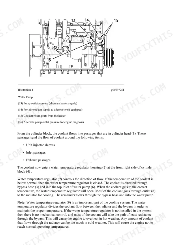
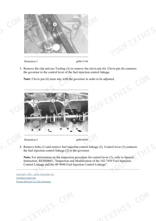
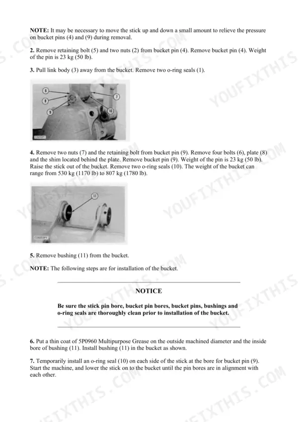
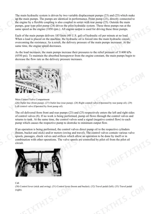
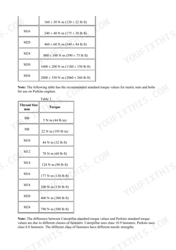
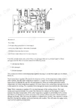
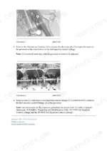
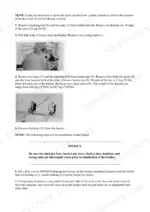
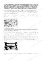

A 3,338 page repair manual set for the Caterpillar E200B and EL200B track-type excavators, serial prefixes 6KF and 4SG (E200B) and 7DF and 5EG (EL200B), all powered by the Cat 3116 diesel. It is a Caterpillar SIS export, several factory books interleaved, each page carrying its own media number. The fold-out schematics at the back are the reason to buy.
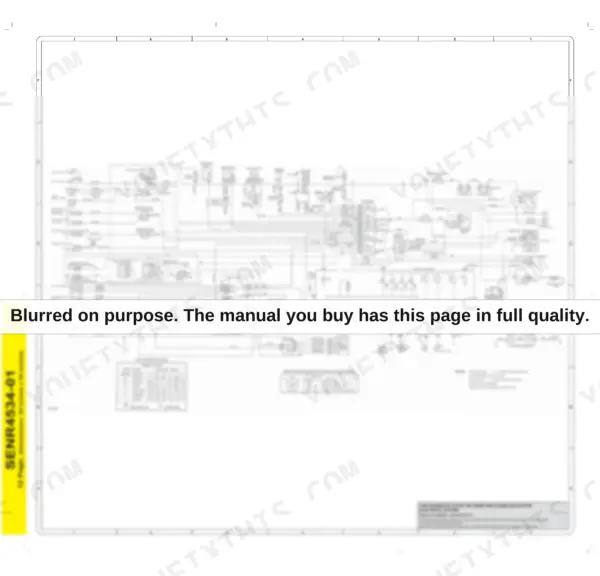
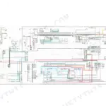
Page 3332 is the SENR4533-01 hydraulic circuit, a 34 x 24 in sheet whose 37-item legend separates the front, rear and pilot pumps, main and pilot relief valves, travel motors and brake valves, swing motor, pilot control valves, solenoid valves I-IV, rotary joint and the boom, stick and bucket cylinders, with a pilot-line location table alongside. It applies to E200B 6KF1-589 and 4SG1-7935 and EL200B 7DF1-1404 and 5EG1-807; page 3338 carries SENR4885-01, the same format, for 6KF590-Up, 4SG7936-Up, 7DF1405-Up and 5EG808-Up. Page 3334 is the SENR4534-01 electrical schematic, 25 x 24 in, with wire-colour code and starter-switch tables, for 6KF1-433, 4SG1-5705, 7DF1-962 and 5EG1-615; page 3336 is SENR4535-01 for the later machines, 6KF434-Up, 4SG5706-Up, 7DF963-Up and 5EG616-Up. The same serial break runs through the main pump and rotary joint procedures.
Two composition facts: 1,406 pages are the generic Cat 3114/3116/3126 engine books, whose covers name IT18F, 446B, D6M and 928F/950F because the same engine is fitted there, and 743 pages are Product Link / EquipmentManager telematics, retrofit tracking hardware and portal administration rather than E200B repair content.
What's Inside This Caterpillar E200B, EL200B Repair Manual
| System | Pages | Key Topics |
|---|---|---|
| Air Inlet & Exhaust System | 1-65 | Turbocharger - Remove and Install, Inlet Manifold Pressure - Test, Exhaust Temperature - Test, Aftercooler - Remove and Install, Exhaust Manifold and Elbow |
| Basic Engine - Specifications, Testing & Rebuild | 66-417 | Engine Valve Lash - Inspect/Adjust, Connecting Rod and Main Bearings - Inspect, Cylinder Block - Inspect, Camshaft and Camshaft Bearings, Crankshaft Rear Seal Carrier, Vibration Damper - Check |
| Cooling System | 418-512 | Cooling System - Check - Overheating, Water Temperature Regulator - Test, Water Pump - Disassemble and Assemble, Engine Oil Cooler - Remove and Install, Hydraulic Oil Cooler, Fan Drive and Fan Assembly |
| Electronic Controller & Starting System - Operation | 513-610 | E200B/EL200B Electronic Controller - Component Description, Fuel Shutoff Solenoid, 37-Mt, 41-Mt and 42-Mt Starting Motors, MUI Engine Governors - Systems Operation |
| Product Link & EquipmentManager (Telematics Portal) | 611-1134 | Product Link Installation, Setup Subscriptions and Manage Users, Asset Watch, Health Watch and Maintenance Watch, Time Fence and Geographic Fence, Fuel Results and Fault Code Reports, Product Link PL522/523 and 121S/300 |
| Electrical - Testing & Adjusting | 1135-1294 | Battery - Test, Charging System - Test, Electric Starting System - Test, Pinion Clearance - Adjust, Wiring Harness (Open and Short Circuit) - Test, Electronic Control Module (ECM) - Flash Program |
| Troubleshooting - Machine, Controller & Diagnostic Codes | 1295-1522 | Problem Sequence Charts a Through M, Checking Procedures (Electronic Power Controller), Starting Motor Does Not Turn or Turns Slowly, Event Code List and Diagnostic Code List, MID 161 CID/FMI Code Entries |
| Electrical - Specifications, Disassembly & Assembly | 1523-1660 | Alternator and Regulator - Remove and Install, Magnetic Pickup, Engine Oil Pressure Sensor - Remove and Install, Ether Starting Aid and Atomizer, Starting Motor - Disassemble - 42-Mt, Jacket Water Heater and Air Inlet Heater |
| Engine Arrangement, Frame & Body | 1661-1688 | Engine Design, Engine Speed - Check, Counterweight, Rotary Joint Installation (6KF1-589, 7DF1-1404), Rotary Joint Installation (6KF590-Up, 7DF1405-Up) |
| Fuel System - Operation, Testing & Adjusting | 1689-1833 | Fuel Ratio Control - Adjust, Fuel Timing Dimension - Adjust, Unit Injector Synchronization - Adjust, Fuel System Pressure - Test, Air in Fuel - Test, Governor Speed and Limiting Circuits |
| Fuel System - Specifications, Disassembly & Assembly | 1834-2378 | Governor Identification - Types I Through VII, Governor Performance Data, Fuel Injection Control Linkage - Remove and Install, Fuel Filter and Water Separator, Fuel Priming Pump - Remove and Install, Governor - Disassemble and Assemble |
| Hydraulic System - Operation, Testing & Troubleshooting | 2379-2642 | Pilot System and Pilot Relief Valve Operation, Main and Line Relief Valve Settings, Negative Flow Control Pump Signal, Operational Tests - Travel, Swing and Cylinder Drift, Checking Procedures (Hydraulic System) |
| Hydraulic System - Specifications, Disassembly & Assembly | 2643-2914 | Cycle Times (New Machine), Main Pump (6KF1-589, 7DF1-1404), Main Pump (6KF590-Up, 7DF1405-Up), Swing Motor and Swing Drive, Travel Motors, Boom, Stick and Bucket Cylinders, Hydraulic and Directional Control Valve, Return, Drain and Pilot Filters |
| Implements & Lubrication System | 2915-2999 | Engine Crankcase Pressure (Blowby) - Test, Engine Oil Pressure - Test, Excessive Engine Oil Consumption - Inspect, Engine Oil Pump - Disassemble, Engine Oil Filter Base and Bypass Valve, Crankcase Breather - Remove and Install |
| Operator Station | 3000-3162 | Cab, Cab Heater, Seat Assembly, Pilot Control Valves (Travel), Hydraulic Activation Control Valve |
| Power Train, Service Equipment & Supplies | 3163-3226 | Travel Brake Valves, Travel Drive Installation, Travel Drive Sprockets, Duo-Cone Seals |
| Torque Specifications | 3227-3274 | Metric (ISO) Fasteners, English (SAE) Fasteners, Straight Thread O-Ring Fittings, O-Ring Face Seal Fittings, Ground Engaging Tool (G.E.T.) Fasteners, Tapered Pipe Thread Fittings |
| Undercarriage & Work Tools | 3275-3330 | Front Idlers, Recoil Springs and Hydraulic Track Adjusters, Idler Adjuster, Track Rollers and Carrier Rollers, Track Assemblies |
| Fold-Out Schematics - Hydraulic & Electrical | 3331-3338 | SENR4533-01 Hydraulic, 6KF1-589 / 7DF1-1404, SENR4885-01 Hydraulic, 6KF590-Up / 7DF1405-Up, SENR4534-01 Electrical, 6KF1-433 / 7DF1-962, SENR4535-01 Electrical, 6KF434-Up / 7DF963-Up |
Quick Reference Specifications
| Specification | Value | Page |
|---|---|---|
| Hydraulic system | ||
| Main relief pressure | 31400 kPa (4600 psi) | p. 1189 |
| Boom raise cycle time, new machine | 3.0 +/- 0.5 sec | p. 2643 |
| Main pump flow, each pump at no load | 183 litres (48 US gal) per minute | p. 2383 |
| Travel circuit | ||
| Travel crossover relief pressure | 33300 kPa (4800 psi) | p. 1189 |
| Cylinder circuits | ||
| Line relief pressure | 33300 kPa (4800 psi) | p. 1189 |
| Swing circuit | ||
| Swing relief pressure | 23500 kPa (3400 psi) | p. 1189 |
| Swing half turn cycle time, new machine | 4.2 sec | p. 2643 |
| Pilot circuit | ||
| Pilot relief valve setting | 3450 kPa (500 psi) | p. 2384 |
| Operational tests | ||
| Test engine speed, high idle no load | 1950 +/- 50 rpm | p. 1188 |
| Machine | ||
| Hydraulic oil tank capacity | 238 litres (63 US gal) | p. 2647 |
| Fuel tank capacity | 280 litres (74 US gal) | p. 2376 |
Caterpillar E200B, EL200B Common Problems This Manual Covers
The machine feels slow and weak, hydraulics take noticeably longer to cycle than they used to.
Run the operational tests for travel, swing and cylinder drift, then time the work cycles against the Cycle Times (New Machine) table: at hi idle 1950 +/- 50 rpm with oil at 50 +/- 5 C, boom raise should take 3.0 +/- 0.5 s, boom lower 2.5 +/- 0.5 s, stick in 4.1 +/- 0.5 s, stick out 2.7 +/- 0.5 s, bucket close 3.5 +/- 0.5 s, bucket dump 2.1 +/- 0.5 s and a half-turn swing 4.2 s. If cycles run slow, test the main relief setting against 31400 kPa (4600 psi) and the pilot relief valve against 3450 kPa (500 psi), then work through the negative flow control pump signal checks.
Manual Section: Hydraulic System - Operation, Testing & Troubleshooting p. 1188Engine will not crank, or the starter turns too slowly to fire the 3116.
Start with the Starting Motor Does Not Turn or Turns Slowly checking procedure, then run Battery - Test, Charging System - Test and Electric Starting System - Test from Electrical - Testing & Adjusting, including Pinion Clearance - Adjust and the Wiring Harness (Open and Short Circuit) - Test. The set covers the 37-MT, 41-MT and 42-MT starting motors, with a 42-MT disassembly procedure in the electrical disassembly and assembly section.
Manual Section: Troubleshooting - Machine, Controller & Diagnostic CodesMachine pulls to one side and tracks crooked when travelling straight.
Run the travel operational test, then verify the travel crossover relief setting, 33300 kPa (4800 psi), to isolate a weak side. From there the set covers the travel motors and travel brake valves, and the undercarriage section handles the mechanical causes: front idlers, idler adjuster, recoil springs and hydraulic track adjusters, track rollers and track assemblies.
Manual Section: Hydraulic System - Operation, Testing & Troubleshooting p. 1209Boom or bucket drifts down when the machine is parked with the controls untouched.
Measure the drift with the cylinder drift operational test, then test the line relief valves against 33300 kPa (4800 psi). If the valve checks pass, follow the disassembly and assembly procedures for the boom, stick and bucket cylinders; the main relief reference for the circuit is 31400 kPa (4600 psi).
Manual Section: Hydraulic System - Specifications, Disassembly & Assembly p. 1189Frequently Asked Questions
My serial number falls mid-range. Which hydraulic and electrical schematic is mine?
Check your serial plate prefix and number against the breaks. Hydraulic: E200B 6KF1-589 and 4SG1-7935 and EL200B 7DF1-1404 and 5EG1-807 use SENR4533-01 on page 3332; 6KF590-Up, 4SG7936-Up, 7DF1405-Up and 5EG808-Up use SENR4885-01 on page 3338. The electrical break comes earlier: 6KF1-433, 4SG1-5705, 7DF1-962 and 5EG1-615 use SENR4534-01 on page 3334; 6KF434-Up, 4SG5706-Up, 7DF963-Up and 5EG616-Up use SENR4535-01 on page 3336. So check both, your machine can sit on different sides of the two breaks. The same serial split applies to the main pump and rotary joint procedures in disassembly and assembly.
Page headers name IT18F, 446B, D6M and 928F/950F. Did I get the wrong manual?
No. 1,406 of the 3,338 pages are Caterpillar's generic 3114/3116/3126 engine books (SENR3583, SENR3582, SENR3611, SENR6454). Their covers name other machines because the same 3116 engine is fitted in the IT18F, 446/446B, D6M and 928F/950F, and Caterpillar published one set of engine books for all of them. Every engine procedure in those pages applies to the 3116 in the E200B and EL200B. The machine-specific books in the set cover the hydraulics, electrics, troubleshooting, operator station and undercarriage.
What is the Product Link section, and do I need it?
743 pages, 22% of the book, are Product Link and EquipmentManager telematics documentation: portal administration, subscriptions and user management, Asset Watch, Health Watch and Maintenance Watch, time and geographic fences, fuel and fault code reports, plus installation, test and troubleshooting for PL522/523 and 121S/300 units. This is retrofit tracking equipment, not E200B repair content. If your machine has no Product Link hardware fitted, you will not use those pages; the rest of the set is machine and engine repair material. p. 611
The monitor is showing a fault code. Can I look it up in this manual?
Yes. The troubleshooting section, pages 1295-1522, carries the Event Code List and Diagnostic Code List, including MID 161 CID/FMI code entries, plus Problem Sequence Charts A through M and the Checking Procedures for the electronic power controller. The Electrical - Testing & Adjusting section backs it up with Wiring Harness (Open and Short Circuit) - Test and Electronic Control Module (ECM) - Flash Program. p. 1295
Does it give real test pressures and cycle times, or just remove-and-install steps?
It gives numbers. Main relief pressure is 31400 kPa (4600 psi); travel crossover relief and line relief are 33300 kPa (4800 psi); swing relief is 23500 kPa (3400 psi); the pilot relief valve setting is 3450 kPa (500 psi); engine oil pressure at low idle 750-850 rpm is approx 100 kPa (15 psi). The Cycle Times (New Machine) table gives targets such as boom raise 3.0 +/- 0.5 s at hi idle 1950 +/- 50 rpm. Capacities are listed too: hydraulic oil tank 238 litres (63 US gal), fuel tank 280 litres (74 US gal). p. 2643

Reviews
There are no reviews yet.