


![Caterpillar 311 repair manual - Electrical & Starting System, [Elec #12-1] Wiper System Problem](https://youfixthis.com/wp-content/uploads/2019/12/caterpillar-311-repair-manual-9lj00262-up-excavator-page-575-300x300.webp)
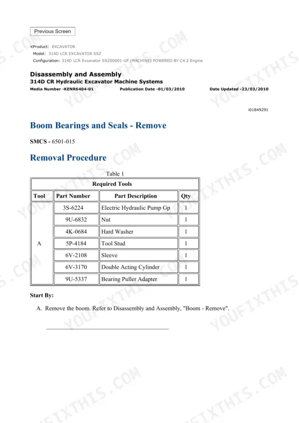
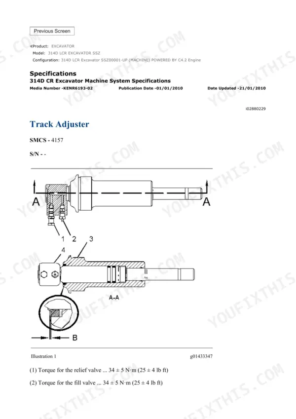
A 5,466-page Caterpillar repair manual set for the 314D LCR and 314D CR hydraulic excavator, serial prefix SSZ00001-UP, powered by the Cat C4.2 engine. It is a Caterpillar SIS export of several factory books interleaved, each page carrying its own media number in the header. The two fold-out schematics are the reason to own it.
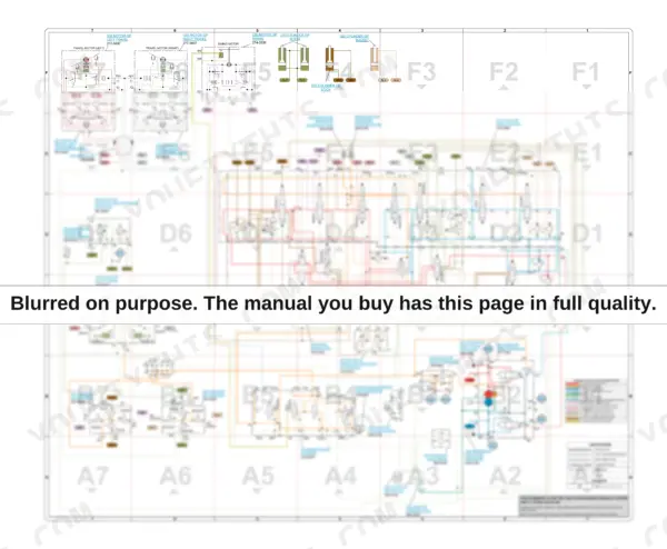
On page 5270 sits the interactive 314D CR hydraulic system schematic, part 270-6045, a full colour circuit where almost every component carries its own Caterpillar part number: main pump 311-7404, main control valve 270-5960, travel motors 277-6697, swing motor 274-2636, swivel 162-4696, joysticks 297-0533 and 297-0532, pilot accumulator 164-6981, case drain filter 288-8194, return oil filter 188-4145, hydraulic tank 282-7220. A colour key separates the circuits, from right and left main pump output and pilot supply through travel speed control, powershift and attachment control to boom, bucket, stick and swing brake control.
On page 5286 is KENR7795, the 48 by 35 inch full colour electrical sheet, part 336-6129, with wire groups colour-coded by function: ground, key-off and key-on circuits, charging, starting, monitor, machine control, security, heater and air conditioner, wiper and washer, and the RS-232 and CAN data links. Measured page by page, the set runs 1,962 pages of machine hydraulic books, 1,443 of machine electronic control, 1,236 of generic C4.2/C6.4 engine books, 417 of air conditioning and 379 of the D Monitor system.
What's Inside This Caterpillar 314D LCR, 314D CR Repair Manual
| System | Pages | Key Topics |
|---|---|---|
| Air Inlet & Exhaust System | 1-82 | Turbocharger - Inspect, Exhaust Temperature - Test, Exhaust Has Excessive Black or White Smoke, Intake Manifold Air Pressure High or Low, Radiator and Aftercooler - Remove |
| Basic Engine - Testing & Rebuild | 83-431 | Engine Performance - Test - Engine Speed, Finding Top Center Position for No. 1 Piston, Compression - Test, Engine Crankcase Pressure (Blowby) - Test, Engine Valve Lash - Inspect/Adjust, Connecting Rod and Bearing Inspection |
| Cooling System | 432-535 | Cooling System - Check - Overheating, Water Temperature Regulator - Test, Engine Oil Cooler - Inspect, Coolant Contains Fuel or Oil, Coolant Temperature Is High |
| Machine Electronic Control - Systems Operation | 536-832 | Electronic Control Module (Machine), Machine ECM for Engine and Hydraulics, Switches, Sensors and Senders, Relays and Related Components, Solenoid Valve (Proportional Reducing) - Power Shift System |
| Electrical - Testing, Calibration & Adjusting | 833-917 | Speed Sensor - Adjust, Charging System - Test, Wiring Harness (Open and Short Circuit) - Test, Electronic Control Module - Flash Program, Configure and Replace, Glossary of Electrical Terms |
| Troubleshooting - Diagnostic & Event Codes | 918-1500 | Electrical Component and Connector Locations, Diagnostic Capabilities, Event Code List, Diagnostic Code List, Using Caterpillar Electronic Technician to Determine Codes, MID 039 CID/FMI Entries |
| Electrical - Specifications, Disassembly & Assembly | 1501-1577 | Alternator and Regulator - Remove and Install, Battery - Remove and Install, Boom Lighting - Remove and Install, Coolant, Fuel and Oil Pressure Sensors, Boost Pressure Sensor |
| Engine Arrangement & Symptom Troubleshooting | 1578-1689 | Welding Precaution, Engine Cranks But Does Not Start, Engine Does Not Crank, Engine Has Mechanical Noise (Knock), Engine Misfires, Runs Rough or Is Unstable, Acceleration or Throttle Response Is Poor |
| Frame, Swing Drive & Upper Structure | 1690-1762 | Swing Bearing Movement - Measure, Counterweight - Remove and Install, Swing Drive - Disassemble and Assemble, Swing Gear and Bearing, Undercarriage Frame - Install |
| Fuel System | 1763-1985 | Air in Fuel - Test, Fuel Injection Timing - Check, Fuel Quality - Test, Fuel System - Prime, Fuel System Diagnostic Codes |
| Hydraulic System - Systems Operation | 1986-2275 | Main and Pilot Hydraulic Systems, Medium Pressure System F3 and F4 Valves, System 20 and System 23 Combined Function, Gear Pump (Pilot), Solenoid Valves |
| Hydraulic System - Testing, Calibration & Work Tool Setup | 2276-2908 | Service Mode - Enter, Work Tool Parameter - Program, Work Tool - Select, Joystick Slide Control - Calibrate, Solenoid Valve (Proportional Reducing) - Calibrate, Negative Flow Control, Default Work Tool Parameter Values |
| Hydraulic System - Symptom & Code Troubleshooting | 2909-3205 | Emerging Symptom Information, Pressure Sensor CID/FMI Entries, Circuit-By-Circuit Fault Isolation |
| Hydraulic System - Specifications, Disassembly & Assembly | 3206-3913 | Accumulator (Pilot) - Remove and Install, Hydraulic Oil Cooler - Remove, Pump Coupling and Auxiliary Pump, Boom and Boom Cylinder Lines, Oil Filter (Hydraulic) - Case Drain, Hydraulic System Pressure Release |
| Implements - Boom, Stick & Bucket Linkage | 3914-4034 | Parallel Offset Boom Hydraulic System, Boom - 4.65 M (15.3 Ft), Boom Bearings and Seals, Power Offset Boom Removal and Installation, Bucket Link and Pin Service, Grease Lines |
| Lubrication System & Machine Arrangement | 4035-4118 | Engine Oil Pressure - Test, Engine Oil Pump - Inspect, Excessive Engine Oil Consumption - Inspect, Oil Pressure Is Low, Oil Temperature Is High |
| Air Conditioning & Heating - Systems Operation | 4119-4431 | Refrigerant Compressor, Refrigerant Condenser, Receiver-Dryer, Refrigerant Expansion Valve, Evaporator Coil and Blower Motor, Actuator and Sensor Operation |
| Air Conditioning & Heating - Testing & Adjusting | 4432-4659 | Machine Preparation for Troubleshooting, Visual Inspection, Guide for Sensors and Actuators, Refrigerant Recovery, Manifold Gauge Set (Refrigerant) - Install, Refrigerant System - Evacuate and Flush |
| Operator Monitor - Code Troubleshooting | 4660-4796 | Using the Operator Monitor to Determine Diagnostic Codes, Monitor and Display CID/FMI Entries |
| Air Conditioning & Heating - Disassembly, Assembly & Capacities | 4797-5081 | Heating and Air Conditioning Unit - Remove and Install, Blower Motor - Remove and Install, Actuator Motor (Damper Assembly), Compressor and Its Mounting, System Capacities for Refrigerant, Air Conditioner Lines |
| Power Train - Final Drive & Travel Motor | 5082-5229 | Travel on Level Ground - Test, Duo-Cone Conventional Seals - Install, Final Drive and Travel Motor - Remove, Travel Circuit Diagnostic Codes |
| Fold-Out Schematics - Hydraulic & Electrical | 5230-5288 | Interactive 314D CR Hydraulic System Schematic, 6045, 314D Excavator with ROPS Electrical System, KENR7795, Air Conditioning Electrical System, Attachment Circuits by Option, Fluid Power and Electrical Graphic Symbols, Component and Tap Location Drawings |
| Service Equipment, Supplies & Torque Specifications | 5289-5379 | Cab Pressurization and Filtration System, Hydraulic Tank and Filter, Fuel Filter Base, Stick Bearings and Seals, Heating and Air Conditioning Service Publications |
| Undercarriage & Work Tools | 5380-5466 | Track Adjuster - Remove and Install, Front Idler and Recoil Spring, Track Carrier Roller, Track Roller (Single Flange), Track Roller Mounting |
Caterpillar 314D LCR, 314D CR Common Problems This Manual Covers
The monitor keeps flashing a CID/FMI code and the machine has gone into a derate or a warning state. I do not know if it is a sensor, a wire or a real failure.
Start in Troubleshooting - Diagnostic & Event Codes, pages 918-1500. It holds the diagnostic code list, the event code list, MID 039 CID/FMI entries, and electrical component and connector locations so you can find the actual sensor or plug. If you are reading the code on the cab display rather than with Caterpillar Electronic Technician, use Operator Monitor - Code Troubleshooting, pages 4660-4796. Wiring harness open and short circuit testing is in pages 833-917.
Manual Section: Troubleshooting - Diagnostic & Event Codes p. 918Fitted a hydraulic breaker and now the tool runs weak and slow, and the rest of the hydraulics feel lazy too.
A new work tool has to be programmed, not just plumbed in. Go to Hydraulic System - Testing, Calibration & Work Tool Setup, pages 2276-2908: enter Service Mode, use Work Tool Parameter - Program and Work Tool - Select, check the default work tool parameter values, and run the joystick slide control and proportional reducing solenoid calibrations. The same section covers negative flow control, which governs how the pump responds to demand.
Manual Section: Hydraulic System - Testing, Calibration & Work Tool Setup p. 2276Machine pulls to one side when tracking on flat ground, one track clearly lazier than the other.
Run the Travel on Level Ground - Test in Power Train - Final Drive & Travel Motor, pages 5082-5229, which also lists the travel circuit diagnostic codes. For circuit-by-circuit fault isolation between pump, travel valves and motors, use Hydraulic System - Symptom & Code Troubleshooting, pages 2909-3205, and trace the travel circuit on the page 5270 schematic, where the travel motors 277-6697 and travel counterbalance valves 303-4484 are labelled. Removal of the final drive and travel motor is in the same power train section.
Manual Section: Power Train - Final Drive & Travel Motor p. 5082Air conditioning blows but does not cool, and in this cab that ends the shift early in summer.
Work through Air Conditioning & Heating - Testing & Adjusting, pages 4432-4659: machine preparation for troubleshooting, visual inspection, the guide for sensors and actuators, installing the manifold gauge set, refrigerant recovery, and evacuating and flushing the system. How the compressor, condenser, receiver-dryer, expansion valve and evaporator work together is in pages 4119-4431, and removal and installation of the unit, blower motor and compressor is in pages 4797-5081.
Manual Section: Air Conditioning & Heating - Testing & Adjusting p. 4432Frequently Asked Questions
Does the hydraulic schematic give me Caterpillar part numbers I can actually order from?
Yes, and that is the strongest page in the set. The interactive hydraulic schematic on page 5270, part 270-6045, labels almost every component with its own Caterpillar part number: main pump 311-7404, main control valve 270-5960, travel motors 277-6697, swing motor 274-2636, swivel 162-4696, travel counterbalance valves 303-4484, joysticks 297-0533 and 297-0532, pilot accumulator 164-6981, pilot travel valve 310-0415, shuttle valve 123-2430, case drain filter 288-8194, pilot filter 158-8987, return oil filter 188-4145, hydraulic tank 282-7220 and the pump pressure sensors 260-2180. You can trace a circuit and read off the part in one look. p. 5270
My monitor is showing a code. Does this manual tell me what it means and what to do, and can I set up a new work tool myself?
Yes on both. Pages 918-1500 cover diagnostic and event codes: the event code list, the diagnostic code list, MID 039 CID/FMI entries, component and connector locations, and how to read codes with Caterpillar Electronic Technician. Pages 4660-4796 cover reading the same codes straight off the operator monitor. For work tools, pages 2276-2908 walk through Service Mode - Enter, Work Tool Parameter - Program, Work Tool - Select, joystick slide control calibration, proportional reducing solenoid calibration and the default work tool parameter values. p. 918
Will this match my machine? Mine is a 314D CR with a serial starting SSZ.
This set is for the 314D LCR and 314D CR compact-radius excavators, serial prefix SSZ00001-UP, with the Cat C4.2 engine. The machine-specific books are titled '314D CR Hydraulic Excavator Machine Systems' and '314D Excavator Hydraulic System', and the electrical schematic KENR7795 is drawn for the 314D excavator with ROPS. If your serial plate starts SSZ, this is the right book.
5,466 pages sounds padded. How much of it is really about my machine?
The composition was measured page by page from the media numbers in the headers, so here it is honestly: 1,962 pages are the machine hydraulic books, 1,443 pages are the machine electronic control books, 1,236 pages are the generic Caterpillar C4.2 and C6.4 engine books shared across models, 417 pages are air conditioning including the all-products R134a book, and 379 pages are the D Monitor monitoring system. So the bulk is machine-specific hydraulics and electronics; the engine and air-conditioning books are broader Caterpillar publications that still apply to this machine.
Is there a proper full-machine wiring diagram, or just fragments?
There is a full sheet. Page 5286 carries KENR7795, the 314D Excavator with ROPS electrical system schematic, part 336-6129, printed as a 48 by 35 inch full colour sheet. Wire groups are colour-coded by function with a printed key: ground, circuits live with the key off, circuits live with the key on, charging, starting, monitor, machine control, security system, heater and air conditioner, wiper and washer, and the RS-232 and CAN data links. It also carries a wire-colour abbreviation table, a symbol table and a harness and cable part-number table. A separate air conditioning electrical schematic and attachment circuits by option sit in the same fold-out section, pages 5230-5288. p. 5230
Reviews
There are no reviews yet.