
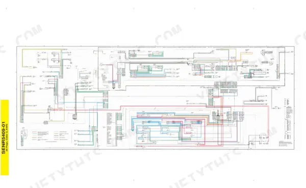
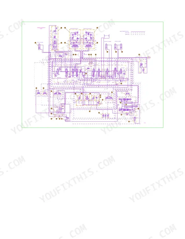
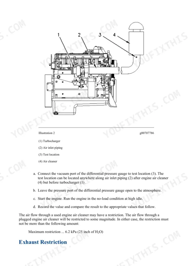
This is the factory repair manual for the Caterpillar 325 and 325L excavators, the 3116 powered machines from Cat's mechanical/hydraulic era. It covers the engine from air cleaner to crankshaft, the full hydraulic system including the main pump regulator and swing control valve, plus swing drive, travel motors, final drives, undercarriage, boom/stick/bucket linkage, and the cab with its HVAC system. The schematics are in the book and both were checked page by page: the full colour electrical system schematic SENR5409-01 on page 3773, and the hydraulic schematic on pages 3848 and 3849, alongside A/C refrigerant troubleshooting. Electrical coverage includes the starting circuit, ELEC circuit code troubleshooting for the onboard monitor, and metric and SAE torque charts. Real numbers throughout, like the 6.2 kPa (25 inch H2O) maximum air inlet restriction spec you will actually use. One honest note about the bundle: about 17.5 percent of the 4043 pages is not repair work on this machine at all, but EquipmentManager dealer software and Product Link telematics documentation, so do not count every page as wrench material.
What's Inside This Caterpillar 325, 325L Repair Manual
| System | Pages | Key Topics |
|---|---|---|
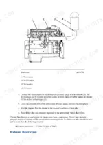
| Air Inlet and Exhaust System | 1-74 | Air Cleaner, Turbocharger, Aftercooler, Air Inlet Manifold, Exhaust Manifold, Exhaust Restriction |
| Basic Engine | 75-452 | Finding Top Center Position for No. 1 Piston, Gear Group (Front) - Time, Engine Crankcase Pressure (Blowby), Compression, Engine Valve Lash, Excessive Bearing Wear, Piston Ring Groove, Connecting Rod Bearings, Main Bearings, Cylinder Block, Flywheel, Flywheel Housing, Vibration Damper |
| Cooling System | 453-554 | Water Temperature Regulator, Water Pump, Engine Oil Cooler, Engine Oil Filter Base, Fan Drive, Fan, Engine Oil Cooler Bypass Valve, Water Temperature Regulator Housing, Water Pump Drive, Radiator |
| Electrical and Starting System (Systems Operation) | 555-639 | Electrical System, Fuel Shutoff Solenoid, Systems Operation, General Information, Component Description, Normal Operation, Disconnect Switch, Battery Circuit, Starting Motor Circuit |
| EquipmentManager (Dealer Diagnostic Software) | 640-1092 | EquipmentManager Dealer Administrator and User Guide (KENR6304-08, KENR6303-08) - NOT Machine Repair Content, Software Install/Configuration for Cat Dealer PCs |
| Electrical and Starting System (Troubleshooting, Interleaved with Product Link) | 1093-1665 | Interleaved, Not Sequential: ELEC Circuit-Code Troubleshooting e.g. PRV Circuit Shorted to Body Ground, Battery Voltage Cable of Swing Priority Solenoid Valve Circuit, Action Alarm Buzzer Circuit, Backup Switches and Starter Switch Diagnosis (~268p); Battery/Charging System/Electric Starting System Test, Starting Motor Solenoid Test, Pinion Clearance Adjust, Wiring Harness Open/Short Circuit Test, ECM Flash Program/Replace (~134p, Recurring Systems Operation/Testing and Adjusting Fragments); Product Link PL522/523 Telematics Troubleshooting, System Overview, Installation/Report Parameters Configure, Wireless Service Configure (~259p, NOT Machine Repair Content) |
| Engine Arrangement | 1666-1687 | General Information, Engine Speed, Engine Design, 4I1042, Solenoid Valve Group, Solenoid Valves, Engine |
| Frame and Body | 1688-1713 | Counterweight, Hood, Roller Mounting, Undercarriage Frame Assembly, Gear and Bearing Group, Swing Gear & Bearing |
| Fuel System | 1714-2451 | Dashpot (Types I, Iii, Iv, V, Vi, And VII), Dual Horsepower (Type VI), Dual Horsepower (Type VII), Fuel Ratio Control (Types I and IV), Fuel Ratio Control (Types V, Fuel Shutoff Solenoid, Fuel Transfer Pump, Governor Bias Spring (Most Types IV, And VI), Governor Bumper Spring (Some Type IV), Governor Limiting Circuit (Types I, Ii, And IV), Governor Limiting Circuit (Types V, Governor Speed Circuit, Governor Servo (Types I |
| Hydraulic System | 2452-3188 | Systems Operation, Hydraulic and Electronic Systems Checking Procedures, Hydraulic System Testing and Adjusting, Introduction, Boom, Stick, Bucket, Swing and Travel, Main Control Valve, Accumulator, Hydraulic Accumulator, Oil Cooler, Counterweight, Main Hydraulic Pump & Pump Drive Coupling, Boom Cylinder, Stick Cylinder, Bucket Cylinder |
| Implements | 3189-3333 | Systems Operation, Testing and Adjusting, Boom Cylinder, Boom Drift Reduction Valve, Boom Group, Boom, Bucket Linkage, Bucket Linkage Group, Stick Group, Stick |
| Lubrication System | 3334-3384 | Engine Crankcase Pressure (Blowby), Engine Oil Pressure, Excessive Engine Oil Consumption, Increased Engine Oil Temperature, Crankcase Breather, Oil Filler, Engine Oil Filter Base, Engine Oil Filter Bypass Valve, Engine Oil Cooler, Engine Oil Pump |
| Operator Station | 3385-3735 | General Information, Identifying the Refrigerant, Identifying the Air Conditioning System, Identifying the Heating System, Refrigerant Expansion Valve System, Refrigerant Orifice Tube System, Refrigerant Compressor, Refrigerant Condenser, Refrigerant Receiver-Dryer, Refrigerant Expansion Valve, In-Line Refrigerant Dryer, Refrigerant Orifice Tube Assembly, Evaporator Coil, Refrigerant Accumulator |
| Power Train | 3736-3771 | Travel Brake Valve, Final Drive, Duo-Cone Seals, Final Drive Sprockets, Final Drives |
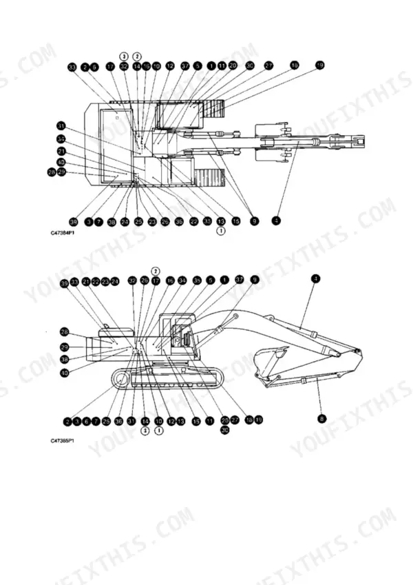
| Schematics | 3772-3882 | Electrical System Wiring Schematic SENR5409-01 (P3773, Applicability Incl. 6KK1-Up), Hydraulic System Schematic SENR5407-01 (p3774-3775/3815-3840, Hydraulic Component-Location Diagram Front/Rear Pump Circuit (p3848-3849), Fluid Power Graphic Symbols Legend, Electrical Power Graphic Symbols Legend |
| Service Equipment and Supplies | 3883-3927 | Cab Pressurization and Filtration System, Manifold Gauge Set (Refrigerant), Heating and Air Conditioning Service Publications, Required Tools, Fuel Filter Base, Fuel Filter (Primary), Fuel Filter and Water Separator, Install, Air Cleaner, Engine Oil Filter Base, Fuel Filter, Fuel Priming Pump, Fuel Priming Pump & Primary Fuel Filter, Duo-Cone Seals |
| Torque Specifications | 3928-3975 | General Information, Metric (ISO) Fasteners, English (SAE) Fasteners, Ground Engaging Tool (G.E.T.) Fasteners, Installation of Fittings, Straight Thread O-Ring Fittings, Plugs, O-Ring Face Seal Fittings, Bulkhead Nuts, Flare Fittings, Air Conditioning Fittings, Air Brake Fittings, Tapered Pipe Thread Fittings, Miscellaneous Fittings |
| Undercarriage | 3976-4028 | Front Idler and Recoil Spring, Front Idlers & Recoil Springs, Front Idlers, Recoil Springs, Hydraulic Track Adjusters, Track Roller, Carrier Roller, Track Carrier Rollers, Track Rollers, Track Assemblies |
| Work Tools | 4029-4043 | Bucket Cylinder, Bucket Adjuster Group, Bucket, Cutting Edge Group, Sidecutter Group, Tip Adapter Group |
Quick Reference Specifications
| Specification | Value | Page |
|---|---|---|
| Maximum air inlet restriction | 6.2 kPa (25 inch of H2O) | p. 13 |
| Maximum back pressure (Standard Exhaust) | 6.7 kPa (27 inch of H2O) | p. 16 |
| Maximum back pressure (Water Cooled Exhaust) | 10 kPa (40 inch of H2O) | p. 16 |
| Aftercooler core water pressure | 240 kPa (35 psi) | p. 26 |
| Exhaust manifold mounting stud torque | 35 ± 5 N·m (26 ± 4 lb ft) | p. 40 |
| Disconnect switch resistance (closed position) | less than 5 ohms | p. 1357 |
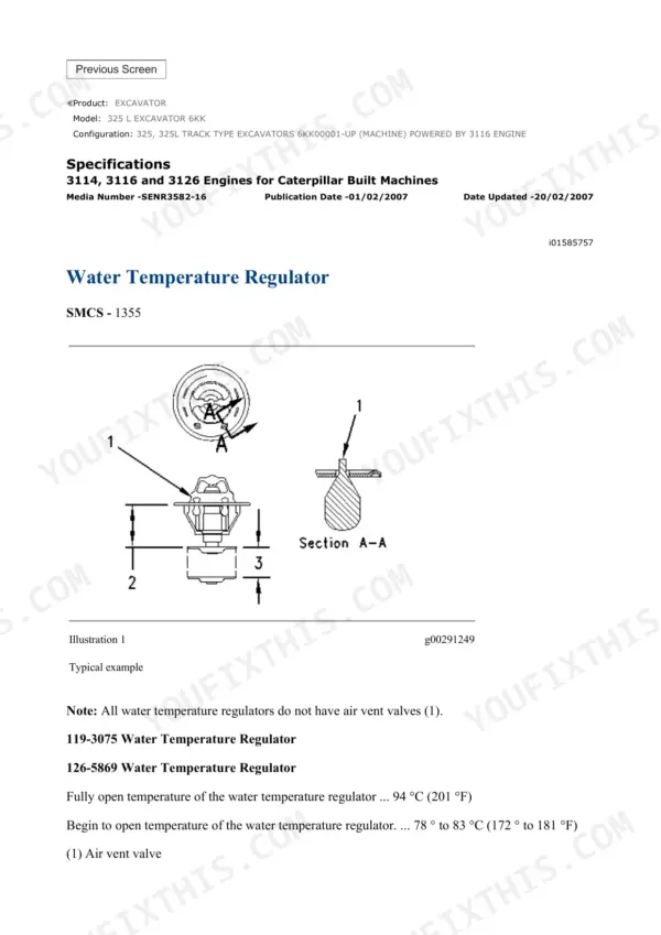
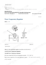
| Water temperature regulator, begin to open / fully open | 78-83 degC (172-181 degF) / 94 degC (201 degF) | p. 497 |
| Travel motor relief valve pressure setting | 36800 ± 980 kPa (5250 ± 140 psi) | p. 3737 |
Caterpillar 325, 325L Common Problems This Manual Covers
Engine running hot or pushing coolant, especially in summer or heavy digging
The Cooling System section covers the radiator, water pump, and thermostat with removal, inspection, and test procedures. Work it in order: check the core for packed debris, pressure test for leaking hoses, then test the water temperature regulator against spec before condemning the pump - it should begin to open at 78-83 degC (172-181 degF) and be fully open by 94 degC (201 degF).
Manual Section: Cooling System p. 497Growling or clunking from a final drive, or the machine pulls to one side when tracking
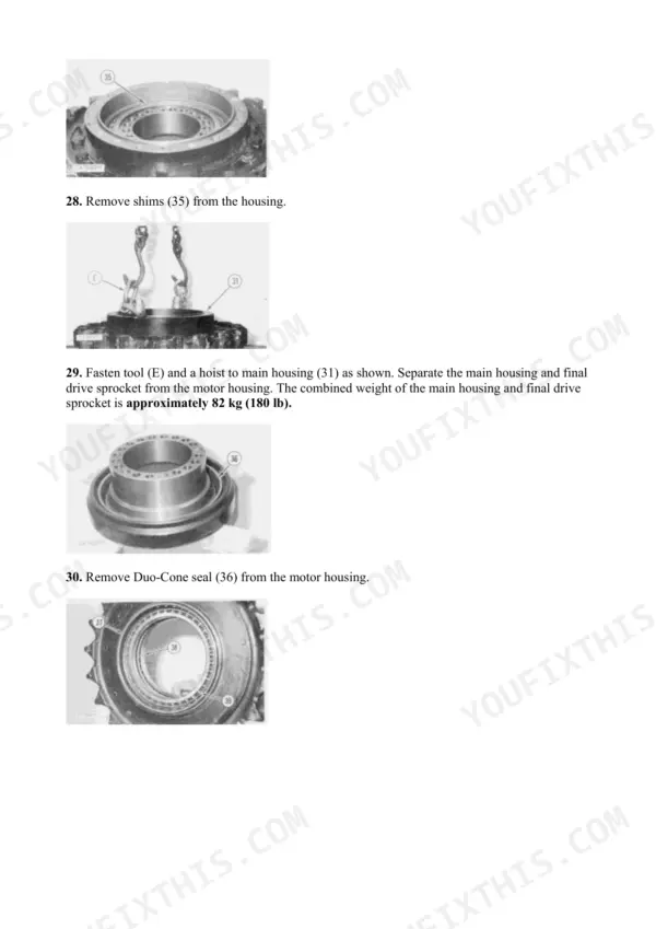
The Power Train section covers the travel motors and final drives, including disassembly and assembly procedures for worn internal parts, bearing damage, and seal failure. The travel motor relief valve pressure setting is 36800 +/- 980 kPa (5250 +/- 140 psi) - a low reading there before you open anything up tells you whether you are chasing the motor or a leaking final drive seal.
Manual Section: Power Train p. 3737Weak or slow hydraulics: sluggish boom, lazy swing, cycle times falling off
The Hydraulic System section gives you the main pump regulator, swing control valve, and relief valve procedures, and the Schematics section holds the full hydraulic schematic on pages 3848 and 3849. Check fluid level and filters first, then test pressures against spec before opening anything up.
Manual Section: Hydraulic System p. 3848No crank or slow crank, intermittent electrical faults, dead machine in the morning
The Electrical And Starting System section troubleshoots the whole starting circuit: battery, cables, ignition switch, and solenoid, with real pass/fail values like the disconnect switch reading less than 5 ohms closed. It also covers the ELEC circuit codes the onboard monitor throws, so you chase the right wire.
Manual Section: Electrical And Starting System p. 1357Frequently Asked Questions
My 325 is down on power and cycle times are slow. Where does the manual tell me to start?
Start on the cheap end. The Air Inlet and Exhaust System section gives the maximum air inlet restriction spec of 6.2 kPa (25 inches of water), so you can test the filter with a gauge instead of guessing. If air and fuel filters check out, move to the Hydraulic System section and run the cycle time checks against the main pump regulator and relief valve procedures. p. 13
The starter will not turn or turns slowly. Does the manual cover diagnosing that?
Yes. The Electrical And Starting System section walks the starting circuit step by step: battery, cables, ignition switch, and starter solenoid. It even gives you a hard number for the disconnect switch, which must read less than 5 ohms in the closed position. That one check catches a lot of no-crank complaints that get misdiagnosed as a dead starter. p. 1357
Is the full hydraulic schematic actually in this manual?
Yes, and this is one of the few copies where that is verified. The hydraulic schematic sits on pages 3848 and 3849 in the Schematics section. You get the whole circuit, so you can trace a lazy swing or a slow stick back through the swing control valve, relief valves, and main pump regulator instead of swapping parts blind. p. 3848
This machine has the Caterpillar electronic monitor. Are the fault codes covered?
Yes. This is a mechanical era machine, so there are no OBD-II codes. The monitor uses Caterpillar's own ELEC circuit code format, and the Electrical And Starting System section includes the ELEC troubleshooting procedures for those circuits, plus EquipmentManager and Product Link telematics documentation for machines that have it fitted. p. 1093
Does it cover the cab air conditioning? Mine blows warm.
It does. The Operator Station section covers the cab, HVAC, seat, and controls, and the Schematics section includes A/C refrigerant troubleshooting. Between the two you can chase a warm cab from the compressor and refrigerant charge through to the control side, which matters when you are in the seat ten hours a day. p. 3385

Reviews
There are no reviews yet.