
This is the full factory repair set for the Cat 232B (SCH02475-up) and 232B2 skid steer with the 3024C engine: Systems Operation, Testing and Adjusting, Disassembly and Assembly, and Specifications in one 4,000-plus page file. The sections you will actually live in are all here - Basic Engine teardown (pages 46-560), the Hydraulic System with the Single Speed schematics (2239-2873), Power Train (3649-4022), Fuel System (2048-2238), and Electrical Diagnostics (1411-1913) with harness open/short tests and the full MID/CID/FMI code list. One honest note: pages 778-1234 are the Product Link/VisionLink dealer portal guide, printed twice back to back - skip past it. Everything a wrench actually needs is in the rest.
Other edition of this manual
What's Inside This Caterpillar 232B, 232B2 Repair Manual
| System | Pages | Key Topics |
|---|---|---|
| Air Inlet and Exhaust System | 1-45 | Naturally Aspirated vs Turbocharged Operation, Air Cleaner Inspection, Exhaust Manifold Removal and Installation, Wastegate Testing |
| Basic Engine | 46-560 | Cylinder Head and Block, Piston and Connecting Rod Specifications, Timing Gear Case, Crankshaft Bearings |
| Cooling System | 561-710 | Cooling System - Check - Overheating, Water Temperature Regulator - Test, Radiator and Hydraulic Oil Cooler, Gear Motor (Fan) - Demand, Water Temperature Regulator - Remove and Install, Water Pump - Install |
| Electrical and Starting System | 711-777 | Ecm, Interlocks, Relays, Starting Circuit - Core Machine Wiring |
| Product Link / VisionLink Dealer Portal (Dealer Software, Not Machine Repair) | 778-1234 | Manage Users, Setup Subscriptions, Equipment Groups, Hardware, Event Tracking, Time Fence and Geographic Fence, Asset Watch, Reports - Printed Twice Back to Back |
| Machine Security System (Immobilizer) | 1235-1410 | Key Programming, Factory Password, System Disarm/Bypass |
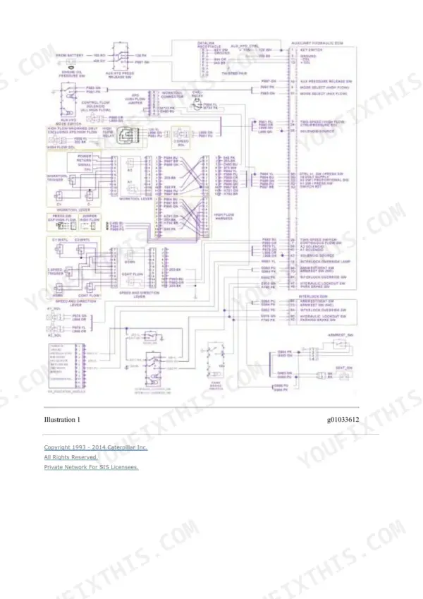
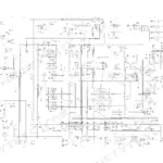
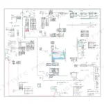
| Electrical Diagnostics, Wiring Schematics and Component Testing | 1411-1913 | System Schematic, Wiring Harness Open/Short Circuit Tests, MID/CID/FMI Diagnostic Codes, Alternator/Starter/Glow Plug Tests |
| Engine Arrangement | 1914-2017 | Engine Design, Troubleshooting, Engine Speed - Check, Engine - Remove, Engine - Install |
| Frame and Body | 2018-2047 | Machine Frame and Mounting, Engine Enclosure, Engine Enclosure - Remove and Install, Lift Arm Cylinder and Mounting |
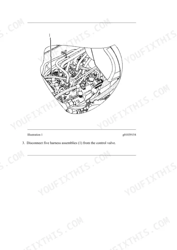
| Fuel System | 2048-2238 | Governor Control, Fuel Quality - Test, Disconnecting Snap to Connect Fittings, Fuel Injection Lines, Fuel Injection Pump - Remove, Fuel Transfer Pump - Remove |
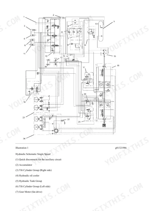
| Hydraulic System | 2239-2873 | Hydraulic Schematic Single Speed Circuit Diagrams, Control Valve, Accumulator, Tilt Cylinder Groups, Pilot Valves |
| Implements | 2874-2899 | Lift Arms - Remove, Lift Arms - Install |
| Lubrication System | 2900-3007 | Engine Crankcase Pressure (Blowby) - Test, Engine Oil Pump - Inspect, Crankcase Breather - Remove and Install, Engine Oil Filter, Engine Oil Relief Valve, Engine Oil Pump |
| Machine Arrangement | 3008-3019 | Heating and Air Conditioning Service Publications, Service Intervals |
| Operator Station | 3020-3648 | Pilot Valve (Joystick), Refrigerant Accumulator, Manifold Gauge Set (Refrigerant) - Remove, Switch (Armrest) and Switch (Seat), System Capacities for Refrigerant (Paving Products), Refrigerant Receiver-Dryer - Remove and Install |
| Power Train | 3649-4022 | Pilot Valve (Joystick), Hydrostatic System Troubleshooting, Hydraulic System Pressure - Release, Tandem Drive, Piston Motor (Hydrostatic) - Remove, Pilot Operated Hydraulic Control - Remove |
| Service Equipment and Supplies | 4023-4038 | Cab Pressurization and Filtration System, Manifold Gauge Set (Refrigerant) - Install, Manifold Gauge Set (Refrigerant) - Remove, Heating and Air Conditioning Service Publications, Required Tools, Fuel Priming Pump and Primary Filter (Water Separator) - Remove and Install |
| Work Tools | 4039-4053 | Coupler Cylinder, Quick Coupler, Quick Coupler - Remove and Install |
Quick Reference Specifications
| Specification | Value | Page |
|---|---|---|
| Inlet and exhaust valve lash | 0.20 mm (0.008 inch) | p. 72 |
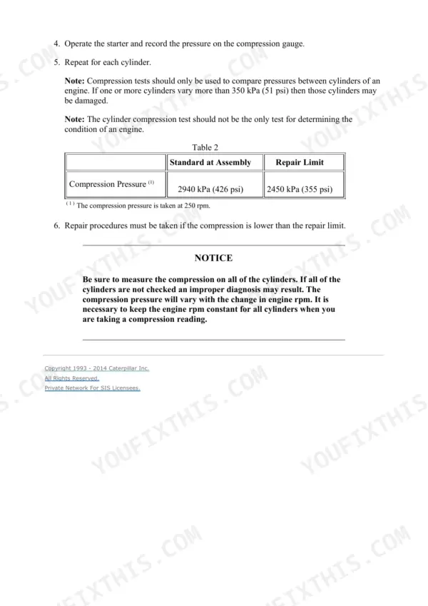
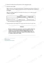
| Cylinder compression, standard at assembly | 2940 kPa (426 psi) | p. 70 |
| Cylinder compression, repair limit | 2450 kPa (355 psi) | p. 70 |
| Cylinder compression, variation limit between cylinders | 350 kPa (51 psi) | p. 70 |
| Cylinder compression test speed | 250 rpm | p. 70 |
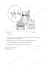
| Exhaust manifold nuts and bolts torque (3024C) | 25 N·m (18 lb ft) | p. 28 |
| Air cleaner hose clamp torque | 4.5 ± 0.5 N·m (40 ± 4 lb in) | p. 21 |
| Turbocharger oil supply tube banjo bolt torque (3024C) | 18 N·m (13 lb ft) | p. 45 |
| Wastegate actuator rod movement | 1.0 mm (0.039 inch) | p. 17 |
| Wastegate actuator test air pressure | 52 kPa (7.5 psi) | p. 17 |
| Fuel injection nozzle leakage test pressure | 2030 kPa (294 psi) below opening pressure | p. 57 |
| Fuel injection nozzle pressure decrease time | 5 to 45 seconds | p. 57 |
| Fuel injection nozzle no-drip time | at least ten seconds | p. 59 |
| Fuel injection nozzle spray angle | 4 degrees from vertical | p. 61 |
| Top center position spacer thickness (No. 1 piston) | 5 mm (0.2 inch) | p. 54 |
Caterpillar 232B, 232B2 Common Problems This Manual Covers
Lift, tilt, or auxiliary hydraulics quit all at once
Check oil level and the seat/interlock switches before condemning the pump - the hydraulic disable circuit kills everything and mimics a dead pump. Then trace the fault on the Hydraulic Schematic Single Speed diagrams and test the control valve and pilot valves per the Hydraulic System section.
Manual Section: Hydraulic System, pages 2239-2873 p. 2240No crank or no start with good battery power
Work the starting circuit tests in Electrical And Starting System - battery connections, relays, ignition switch, and interlock wiring in that order. If cranking is fine but there is no fire, check whether the Machine Security System immobilizer is armed before tearing into the fuel side.
Manual Section: Electrical And Starting System, pages 711-777Overheating under load
These machines pack the radiator and oil cooler where debris cakes the fins, so clean the cores and check coolant level first. Then follow the Cooling System section's testing procedures to check the components in order instead of throwing a water pump at it on a hunch.
Manual Section: Cooling System, pages 561-710 p. 561Intermittent electrical gremlins and random sensor faults
Pull the active MID/CID/FMI codes, then run the wiring harness open and short circuit tests from the Electrical Diagnostics section against the system schematic. Most intermittents on these machines are corroded or loose connectors, and the harness tests find them faster than swapping modules.
Manual Section: Electrical Diagnostics, Wiring Schematics and Component Testing, pages 1411-1913 p. 1411Frequently Asked Questions
What do the fault codes on a Cat 232B/232B2 mean and how do I clear them?
The Electrical Diagnostics section (pages 1411-1913) lists the MID/CID/FMI codes this machine reports and walks you through the harness open and short circuit tests to confirm the fault. Codes do not really 'clear' with a trick - fix the cause and the active code goes away. Chasing the wiring test first saves you from replacing a good sensor.
What is the banjo bolt torque in this manual, and why do I see two different values?
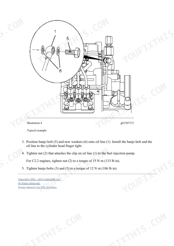
There is no contradiction once you see which fastener each value belongs to. Page 45, in the 3024C turbocharger installation, tightens the oil supply tube banjo bolt to 18 N.m (13 lb ft). The 12 N.m (106 lb in) figure you may spot on page 2964 is for engine oil line banjo bolts, and it comes from the C2.2 engine Disassembly and Assembly publication (KENR6948-01) that Caterpillar bundled into this SIS export. Your machine has the 3024C, so do not carry the C2.2 numbers over. p. 45
The machine has electrical power but the engine will not start. Where do I look?
Start with the Electrical And Starting System section (pages 711-777) - starting circuit, relays, and interlocks are core machine wiring here. Do not forget the Machine Security System (pages 1235-1410): if the immobilizer is armed or a key was never programmed, it will kill the start with everything else looking fine. Disarm and bypass procedures are in that section.
What are the valve lash and compression specs for the 3024C in this machine?
Valve lash is 0.20 mm (0.008 inch) for both inlet and exhaust, on page 72. Standard cylinder compression at assembly is 2940 kPa (426 psi), with a repair limit of 2450 kPa (355 psi), on page 70. Both come from the Basic Engine section (pages 46-560), which also covers cylinder head, piston and rod specs, and crankshaft bearings for a full rebuild. p. 70
Does this manual cover key programming and the security system?
Yes. The Machine Security System section (pages 1235-1410) covers key programming, the factory password procedure, and how to disarm or bypass the immobilizer. Handy if you bought a used machine with one key and a previous owner you cannot reach. p. 1235
Reviews
There are no reviews yet.