


A Caterpillar SIS export of the factory repair manuals for the 320, 320L, 320N and 320S excavators (serial prefixes 4ZJ, 3XK, 9WG and 6KM), 3,965 pages of interleaved Cat service books built around the 3116 engine.
Get the serial split right before anything else: the electrical schematic comes in two versions, SENR5459 for the 320L from 3XK1-Up and SENR6242 for the 320L from 3XK1909-Up, and the hydraulic fold-out is SENR8742, the 3XK1909-Up version.
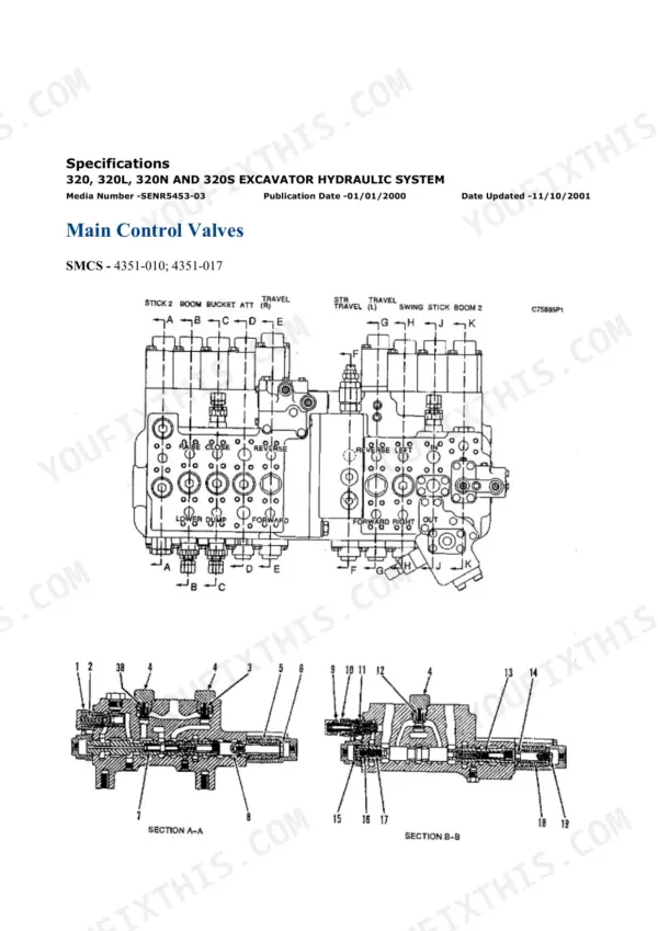
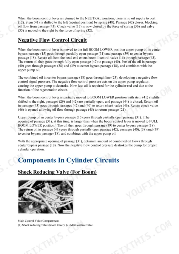
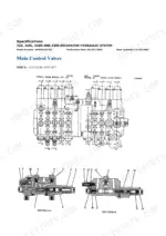
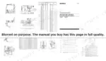
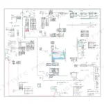
The SENR6242 sheet carries harness connector and component location drawings for Areas A to F, a Component Location table tying each component to its schematic grid reference and its place on the machine, a Harness Connector Location table listing every connector by contact count, and the symbol keys for both schematic and harness wiring. The SENR8742 sheet identifies the numbered items on the hydraulic circuit, including the stacked main control valve sections and the pilot oil manifold with its ports labelled. On the page count, plain facts: 1,523 pages are the generic Caterpillar 3114/3116/3126 engine books, 743 pages are Product Link and EquipmentManager telematics, and 565 pages are air-conditioning and heating manuals, two of which are all-machines Cat A/C books rather than 320-specific ones. The remainder is the machine itself: hydraulic testing and adjusting with cycle times and relief pressures, fuel system and governor work, electrical testing, boom and stick groups, and the undercarriage.
What's Inside This Caterpillar 320, 320L, 320N, 320S Repair Manual
| System | Pages | Key Topics |
|---|---|---|
| Contents & Section Index | 1-42 | Group Index for Every System, Media Numbers of the Bundled Manuals |
| Air Inlet & Exhaust System | 43-113 | Turbocharger - Inspect, Inlet Manifold Pressure - Test, Exhaust Temperature - Test, Aftercooler - Remove and Install, Air Cleaner and Muffler |
| Basic Engine - Operation, Testing & Rebuild | 114-508 | Finding Top Center Position for No. 1 Piston, Compression - Test, Engine Crankcase Pressure (Blowby) - Test, Engine Valve Lash - Inspect/Adjust, Connecting Rod and Main Bearings - Inspect, Cylinder Block - Inspect, Flywheel and Flywheel Housing - Inspect, Vibration Damper - Check |
| Cooling System | 509-612 | Cooling System - Check - Overheating, Water Temperature Regulator - Test, Water Pump - Test, Engine Oil Cooler - Remove and Install, Fan Drive and Fan |
| Electrical & Starting System - Systems Operation | 613-697 | Electrical System Component Description, Fuel Shutoff Solenoid, Pressure Switch (Refrigerant), Normal Operation of the Machine Circuits |
| Product Link & EquipmentManager (Telematics Portal) | 698-1221 | Product Link Installation, Setup Subscriptions and Manage Users, Manage Equipment Groups and Hardware, Asset Watch and Health Watch, Time Fence and Geographic Fence, Event Tracking and Uploaded Data |
| Electrical - Testing & Adjusting | 1222-1462 | Battery - Test, Charging System - Test, Electric Starting System - Test, Pinion Clearance - Adjust, No Load - Test, Starting Motor Solenoid - Test, Brush and Brush Holder - Check |
| Troubleshooting - Machine Systems & Product Link | 1463-1714 | Electronic Control Module (ECM) - Flash Program and Replace, Wiring Harness (Open and Short Circuit) - Test, Electrical Connector - Inspect, Starting Motor Does Not Turn or Turns Slowly, Electronic Service Tool Does Not Communicate with ECM, Position Reports and Reporting-Interval Faults |
| Electrical - Specifications, Disassembly & Assembly | 1715-1843 | Alternator - Remove and Install, Jacket Water Heater and Air Inlet Heater, Magnetic Pickup, Solenoid Valve Group, Engine Oil Pressure Sensor - Remove and Install, Ether Starting Aid and Atomizer |
| Engine Arrangement, Frame & Body | 1844-1881 | Engine Design, Engine Speed - Check, Hood, Swing Gear and Bearing, Boom and Stick Grease Lines Group |
| Fuel System - Systems Operation | 1882-1928 | Governor Speed Circuit, Governor Limiting Circuit, Fuel Ratio Control, Dual Horsepower, Fuel Transfer Pump, Torque Limiter Device |
| Fuel System - Testing & Adjusting | 1929-2026 | Air in Fuel - Test, Fuel Quality - Test, Fuel System Pressure - Test, Fuel Timing Dimension - Adjust, Unit Injector Synchronization - Adjust, Governor Calibration Bench Setup and Load Stop Dimension |
| Fuel System - Specifications, Disassembly & Assembly | 2027-2607 | Governor Identification - Types I Through VII, Fuel Injection Control Linkage - Remove and Install, Governor Control Motor, Fuel Filter and Water Separator, Fuel Priming Pump and Primary Filter, Governor Disassembly by Type |
| Hydraulic System - Systems Operation | 2608-2771 | Pilot Circuit and Pilot Relief Valve, Negative Flow Control Pump Signal, Main Control Valve and Implement Circuits, Power Mode Selector Operation |
| Hydraulic System - Testing & Adjusting | 2772-2995 | Cycle Times (New Machine), Line Relief Pressure Adjustment, Power Shift Pressure Calibration, Accumulator and Oil Cooler Checks, Boom, Stick and Bucket Cylinder Drift |
| Hydraulic System - Specifications, Disassembly & Assembly | 2996-3082 | Main Pump, Travel Motor, Swing Drive, Hydraulic Tank, Return and Pilot Filters, Travel Brake Valves |
| Implements, Lubrication System & Machine Arrangement | 3083-3199 | Boom Group and Stick Group, Bucket Linkage, Stick Drift Reduction Valve, Engine Oil Pressure - Test, Excessive Engine Oil Consumption - Inspect, Crankcase Breather |
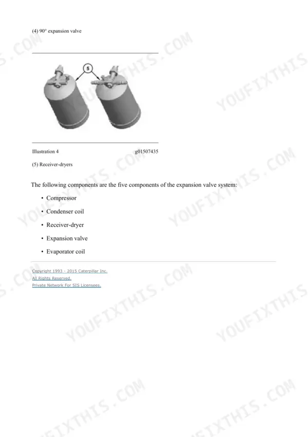
| Air Conditioning & Heating - Systems Operation | 3200-3299 | Identifying the Air Conditioning System, Refrigerant Compressor, Refrigerant Condenser and Evaporator Coil, Expansion Valve and Orifice Tube Systems, Receiver-Dryer, Heating System Schematic |
| Air Conditioning & Heating - Testing & Adjusting | 3300-3529 | Refrigerant Recovery, Manifold Gauge Set (Refrigerant) - Install, Refrigerant System - Evacuate and Charge, Refrigerant Leakage - Test, Air Conditioning Performance - Test, Refrigerant Oil - Test |
| Air Conditioning & Heating - Troubleshooting | 3530-3593 | Machine Preparation for Troubleshooting, Visual Inspection, Heating System Troubleshooting, Condensate Drainage System |
| Air Conditioning & Heating - Specifications, Disassembly & Assembly | 3594-3733 | System Capacities for Refrigerant, Refrigerant Oils and R-12 Refrigerant, Compressor - Remove and Install, Accumulator - Remove and Install, In-Line Refrigerant Dryer - Remove and Install, Component Locations |
| Power Train, Cab Filtration & Service Supplies | 3734-3835 | Final Drive and Final Drive Sprockets, Duo-Cone Seals, Cab Pressurization and Filtration System, Cab Air Filters, Heating and Air Conditioning Service Publications |
| Undercarriage & Work Tools | 3836-3944 | Front Idlers and Recoil Springs, Hydraulic Track Adjusters, Track Rollers and Carrier Rollers, Track Assemblies, Undercarriage Frame Assembly, Bucket Adjuster Group and Cutting Edge Group |
| Fold-Out Schematics - Hydraulic & Electrical | 3945-3965 | SENR5459 Electrical, 320L 3XK1-Up, SENR6242 Electrical, 320L 3XK1909-Up, SENR8742 Hydraulic, Attachment Circuits: Fine Swing, Two-Speed Hammer, Boom Lowering Check Valve, Single Action, Double Action, One-Pump and Two-Pump Attachment Piping |
Quick Reference Specifications
| Specification | Value | Page |
|---|---|---|
| Hydraulic system | ||
| Cycle time, boom raise (new machine) | 3.0 +/- 0.5 seconds | p. 2976 |
| Cycle time, stick in (new machine) | 3.8 +/- 0.5 seconds | p. 2976 |
| Cycle-time test engine setting | high idle 1970 +/- 20 rpm, oil 55 +/- 5 C | p. 2976 |
| Line relief valve pressure | 33 800 +/- 1470 kPa (4900 +/- 215 psi) | p. 2946 |
| Main pump output | 179 +/- 3 litre/min (47 +/- 0.8 U.S. gpm) at 9800 kPa (1425 psi), pump 1800 rpm | p. 3033 |
| Operational test conditions | no-load high idle 1860 +/- 50 rpm, oil 55 +/- 5 C (130 +/- 9 F) | p. 2925 |
| Swing circuit | ||
| Cycle time, 180 degree swing | 4.2 seconds maximum | p. 2976 |
| Travel circuit | ||
| Travel time over 20 m (66 ft) | 14 seconds max at HIGH, 22 seconds max at LOW | p. 2976 |
| Travel brake valve relief setting | 36 800 +/- 1470 kPa (5336 +/- 213 psi) | p. 3040 |
| Pilot circuit | ||
| Pilot relief valve setting | 3450 kPa (500 psi) | p. 2679 |
| Machine | ||
| Hydraulic oil tank capacity | 136 litres (36 U.S. gal) | p. 3932 |
Caterpillar 320, 320L, 320N, 320S Common Problems This Manual Covers
Everything moves, but slower than it should, and the machine feels weak under load.
Start with the cycle time test on page 2976. On a new machine at high idle 1970 +/- 20 rpm with oil at 55 +/- 5 C in POWER MODE III, boom raise is 3.0 +/- 0.5 s, boom lower 3.2 +/- 0.5 s, stick out 2.5 +/- 0.5 s, stick in 3.8 +/- 0.5 s, bucket close 3.8 +/- 0.5 s, bucket open 2.0 +/- 0.5 s, and a 180 degree swing takes 4.2 s maximum. If your times run long, test the main pump: output should be 179 +/- 3 litre/min (47 +/- 0.8 U.S. gpm) at a delivery pressure of 9800 kPa (1425 psi) in power mode 3, with power shift pressure 1770 +/- 50 kPa (255 +/- 7 psi) and the pump at 1800 rpm. Then check line relief valve pressure against 33 800 +/- 1470 kPa (4900 +/- 215 psi).
Manual Section: Hydraulic System - Testing & Adjusting p. 2976The machine pulls to one side when travelling and will not track straight on flat ground.
Run the travel time test on page 2976: over 20 m (66 ft) after a 5 m (17 ft) run, the machine should take 14 seconds maximum at HIGH speed and 22 seconds maximum at LOW speed. A side that lags points you at that side's travel circuit. The travel brake valve relief setting is 36 800 +/- 1470 kPa (5336 +/- 213 psi), and the travel brake valves and travel motor are covered in the hydraulic specifications, disassembly and assembly book. Uneven track tension does the same thing, and the hydraulic track adjusters are covered under Undercarriage & Work Tools.
Manual Section: Hydraulic System - Specifications, Disassembly & Assembly p. 2996The boom settles and the bucket creeps down whenever the machine sits for a few minutes.
The manual carries boom, stick and bucket cylinder drift checks. Run them at the standard operational test conditions from page 2925, no-load high idle 1860 +/- 50 rpm and hydraulic oil at 55 +/- 5 C (130 +/- 9 F), so the readings are comparable. If drift traces back to a relief valve, the line relief valve pressure spec is 33 800 +/- 1470 kPa (4900 +/- 215 psi) on page 2946. The Stick Drift Reduction Valve itself is covered under Implements, Lubrication System & Machine Arrangement.
Manual Section: Hydraulic System - Testing & Adjusting p. 3083Turn the key and nothing happens, or it cranks slowly and starts hard.
Work through the electrical tests in order: Battery - Test, Charging System - Test, Electric Starting System - Test, Starting Motor Solenoid - Test, Pinion Clearance - Adjust and Brush and Brush Holder - Check. The troubleshooting book adds a dedicated Starting Motor Does Not Turn or Turns Slowly procedure, the Wiring Harness (Open and Short Circuit) - Test and Electrical Connector - Inspect, which matter on a thirty-year-old harness. If it cranks well but still starts hard, move to the fuel side: Air in Fuel - Test, Fuel Quality - Test and Fuel System Pressure - Test in Fuel System - Testing & Adjusting.
Manual Section: Electrical - Testing & AdjustingFrequently Asked Questions
My 320L is below serial 3XK1909. Which electrical schematic applies to my machine?
The set carries both versions, on the fold-out pages 3945-3965. SENR5459 covers the 320L from 3XK1-Up and SENR6242 covers the 320L from 3XK1909-Up. This product starts at S/N 3XK00822, so if your serial number is below 3XK1909 you work from the SENR5459 sheet, and at 3XK1909 or above you work from SENR6242. The hydraulic fold-out, SENR8742, is the 3XK1909-Up version. p. 3945
Out of 3,965 pages, how much is actually about repairing the excavator?
Counted from the printed media numbers on each page: 1,523 pages are the generic Caterpillar 3114/3116/3126 engine books, 743 pages are Product Link and EquipmentManager telematics, and 565 pages are air-conditioning and heating manuals, two of which cover all Caterpillar machines rather than the 320 specifically. The engine books still apply to your machine, since the 320 family runs the 3116, and the telematics portal section you can simply skip. The machine-specific hydraulic, electrical, fuel, implement and undercarriage books make up the rest. p. 1
Does it give the actual hydraulic pressure settings, or just tell me to see the dealer?
The settings are printed. Line relief valve pressure is 33 800 +/- 1470 kPa (4900 +/- 215 psi), the pilot relief valve setting is 3450 kPa (500 psi), and the travel brake valve relief setting is 36 800 +/- 1470 kPa (5336 +/- 213 psi). The Hydraulic System - Testing & Adjusting section (pages 2772-2995) covers line relief pressure adjustment, power shift pressure calibration and the cycle time checks for a new machine, so you can measure your machine against the factory numbers. The hydraulic oil tank holds 136 litres (36 U.S. gal). p. 2946
Will this get me through a 3116 rebuild, not just adjustments?
The Basic Engine section (pages 114-508) runs from operation and testing into rebuild work: finding top center position for the No. 1 piston, Compression - Test, engine crankcase pressure (blowby) test, valve lash inspection and adjustment, connecting rod and main bearing inspection, cylinder block inspection, and flywheel and flywheel housing checks. Fuel system coverage goes deeper still, with governor identification for Types I through VII and governor disassembly by type at pages 2027-2607, plus fuel timing dimension adjustment and unit injector synchronization in Fuel System - Testing & Adjusting. p. 114
Is the undercarriage covered, tracks and rollers included?
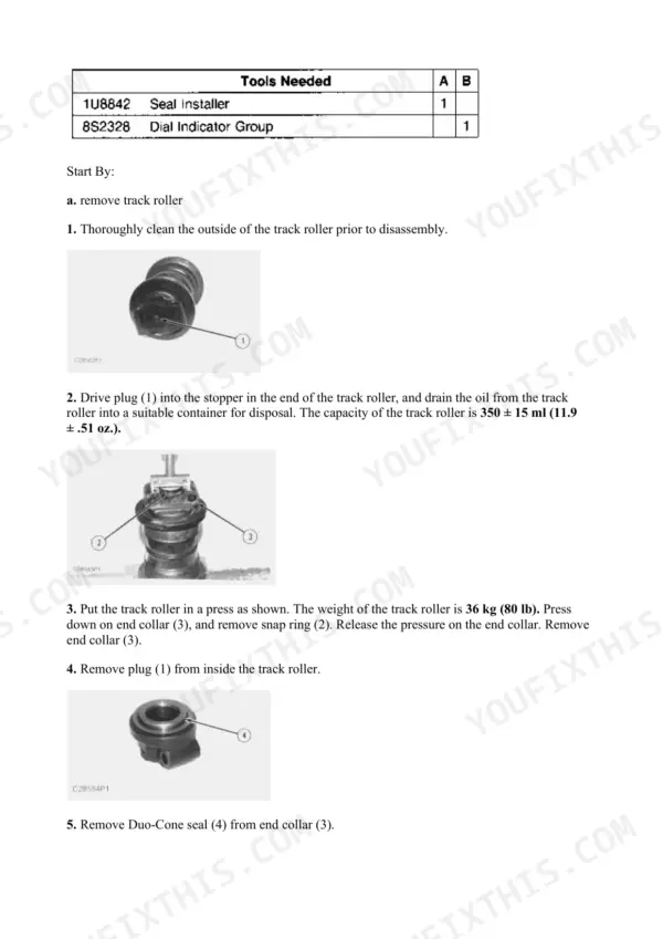
Yes. Pages 3836-3944 cover front idlers and recoil springs, hydraulic track adjusters, track rollers and carrier rollers, track assemblies, the undercarriage frame assembly, and the bucket adjuster and cutting edge groups. Final drives, final drive sprockets and Duo-Cone seals are in the Power Train section at pages 3734-3835. p. 3836

Reviews
There are no reviews yet.