

A 5,761 page Caterpillar repair manual set for the 329D L and 329D LN excavators, serial prefixes XDB and EBM, built around the Caterpillar C7 engine. It is a Caterpillar SIS export with one unusual and useful trait: the fold-out schematics sit at the front of the book, pages 1 to 72, not buried at the back.
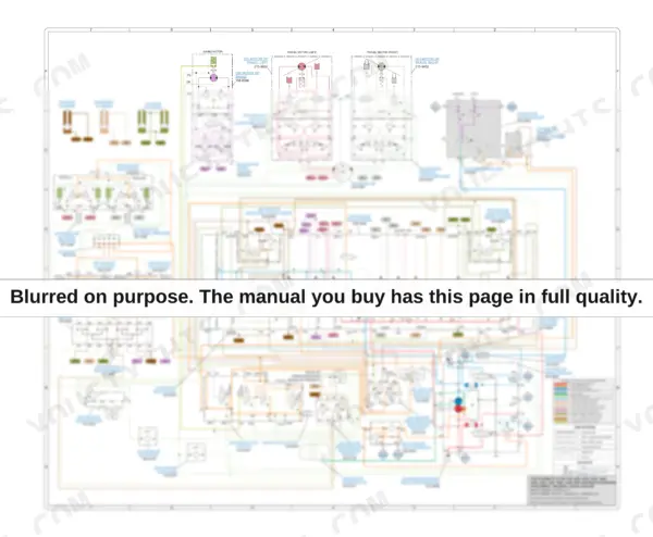
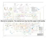
Page 9 is the colour hydraulic schematic for the universal quick coupler attachment, and the components on the circuit carry their own Caterpillar part numbers: main hydraulic pump 272-6955, main control valve 259-7602, swing motor 158-8986, travel motors 215-9952, quick coupler valve 254-3080 with its solenoid 258-6749, joysticks 232-4100 and 225-4813, accumulator 164-6981.
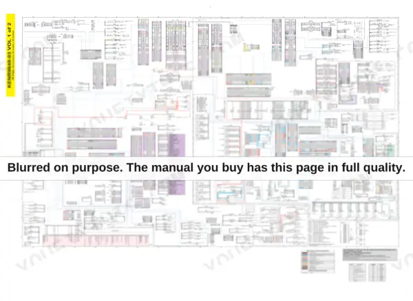
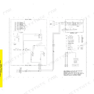
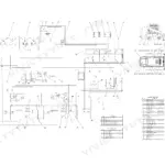
Page 25 is volume 1 of 2 of the electrical system, a 48 by 35 inch colour sheet of cab and chassis wiring with a printed colour key, a wire colour abbreviation table and numbered application notes. The composition was measured page by page from the media number printed in each header, so it is known rather than guessed: 2,537 pages are the machine hydraulic and machine-systems books, including '325D and 329D Excavators Machine System Specifications' and the hydraulic system volumes, 1,146 pages are the generic Caterpillar C7 engine books, 625 pages are the machine electronic control system, 484 pages are air conditioning, 468 pages are the tool control system, whose covers name the 340D and 340D2, and 379 pages are the D Monitor monitoring system.
What's Inside This Caterpillar 329D L, 329D LN Repair Manual
| System | Pages | Key Topics |
|---|---|---|
| Fold-Out Schematics & Graphic Symbols | 1-72 | Colour Hydraulic Schematic for the Universal Quick Coupler Attachment, Colour Electrical Schematic, Cab and Chassis Wiring, Volumes 1 and 2, Component and Tap Location Drawings, Fluid Power Graphic Symbols, Electrical Power Graphic Symbols, Machine Component Location |
| Air Inlet & Exhaust System | 73-182 | Turbocharger - Inspect, Inlet Manifold Pressure - Test, Aftercooler - Test, Engine Has Early Wear, Engine Oil in Exhaust System |
| Basic Engine - Testing & Rebuild | 183-452 | Engine Performance - Test - Engine Speed, Finding Top Center Position for No. 1 Piston, Gear Group (Front) - Time, Compression - Test, Engine Valve Lash - Inspect/Adjust, Excessive Bearing Wear - Inspect |
| Cooling System | 453-572 | Cooling System - Check - Overheating, Water Temperature Regulator - Test, Water Pump - Test, Coolant in Engine Oil, Coolant Temperature Is Too High |
| Machine Electronic Control - Systems Operation | 573-889 | Electronic Control Module (Machine), Machine ECM for Engine and Hydraulics, Switches and Sensors, Diagnostic Operation, Related Components |
| Electrical - Testing, Calibration & Adjusting | 890-956 | Speed Sensor - Adjust, Charging System - Test, Wiring Harness (Open and Short Circuit) - Test, Electronic Control Module (ECM) - Configure, Glossary of Electrical Terms |
| Troubleshooting - Diagnostic Codes | 957-1400 | Electrical Component and Connector Locations, Diagnostic Capabilities, Diagnostic Code List, Using Caterpillar Electronic Technician to Determine Codes, MID 039 CID/FMI Entries |
| Electrical Components & Engine Symptom Troubleshooting | 1401-1533 | Alternator - Remove and Install with the Engine in the Machine, Engine Electronic Control - Remove and Install, Speed/Timing Sensor - Remove and Install, Liquid Level Sensor (Water Separator), Engine Cranks But Will Not Start, Engine Stalls at Low RPM, Excessive Black Smoke |
| Frame, Swing Drive & Counterweight | 1534-1644 | Swing Bearing Movement - Measure, Counterweight - Remove and Install, Swing Drive - Disassemble and Assemble, Swing Hydraulic Circuit |
| Fuel System | 1645-1851 | Air in Fuel - Test, Electronic Unit Injector - Test, Fuel Quality - Test, Fuel System - Prime, Fuel System Pressure - Test |
| Hydraulic System - Systems Operation | 1852-2227 | Main and Medium Pressure Hydraulic Systems, System 13 and System 17 Combined Function, System 16 One-Way Two Pump, Solenoid Valves |
| Hydraulic System - Testing, Calibration & Work Tool Setup | 2228-2731 | Service Mode - Enter, Process for Setting Up the Work Tool, Work Tool Parameter - Program, Work Tool - Select, Control (Pedal) - Calibrate |
| Hydraulic System - Symptom & Code Troubleshooting | 2732-2945 | Emerging Symptom Information, Pressure Sensor CID/FMI Entries, Circuit-By-Circuit Isolation |
| Hydraulic - Pumps, Cooler, Lines & Travel Motor | 2946-3550 | Gear Pump (Auxiliary) - Remove and Assemble, Pump Coupling, Hydraulic Oil Cooler and Radiator - Remove and Install, Boom, Bucket, Stick and Pilot Lines, Travel Motor - Assemble, Main Hydraulic Pump - Remove, Control Manifold (Pilot Oil) - Remove |
| Hydraulic - Control Valves, Relief Valves & Tank | 3551-4164 | Hydraulic Tank - Install, Control Valve (Auxiliary) - Disassemble and Assemble, Control Valve (Auxiliary) - Medium Pressure, Relief Valve (Negative Flow Control), Control Valve (Boom Lowering), Main Control Valve - Disassemble |
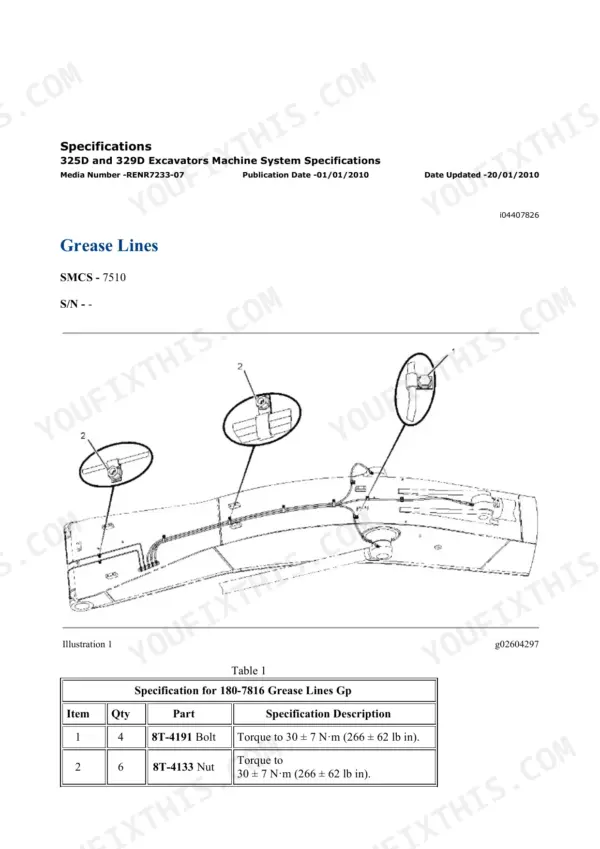
| Implements - Boom, Stick & Bucket Linkage | 4165-4261 | Boom - 5.55 M (18.209 Ft), Boom - 6.15 M (20.2 Ft), Fore Boom Group, Boom Bearings and Seals, Bucket Link and Pin Service, Grease Lines |
| Lubrication System & Machine Arrangement | 4262-4342 | Engine Oil Pressure - Test, Engine Oil Pump - Inspect, Increased Engine Oil Temperature - Inspect, Engine Oil in Cooling System |
| Air Conditioning & Heating - Systems Operation | 4343-4665 | Refrigerant Compressor, Refrigerant Condenser, Receiver-Dryer, Refrigerant Expansion Valve, Evaporator Coil, Pressure Switch (Refrigerant Pressure Cutoff) |
| Air Conditioning & Operator Monitor - Code Troubleshooting | 4666-4999 | Machine Preparation for Troubleshooting, Visual Inspection, E11 and E12 Recirculation Sensor Faults, E13 and E14 Fresh Air Sensor Faults, Using the Operator Monitor to Determine Diagnostic Codes, Monitor and Display CID/FMI Entries |
| Air Conditioning & Heating - Disassembly, Assembly & Capacities | 5000-5358 | Heating and Air Conditioning Unit - Remove and Install, Refrigerant Compressor - Remove and Install, Air Conditioner Lines, System Capacities for Refrigerant, Compressor and Heater Mounting |
| Power Train - Final Drive & Travel | 5359-5504 | Travel on Level Ground - Test, Duo-Cone Conventional Seals - Install, Final Drive - Remove and Disassemble, Travel Symptom Troubleshooting |
| Service Equipment, Supplies & Torque Specifications | 5505-5607 | Cab Pressurization and Filtration System, Air Cleaner - Precleaner, Hydraulic Tank and Filter, Manifold Gauge Set (Refrigerant) - Install, Service Information Report |
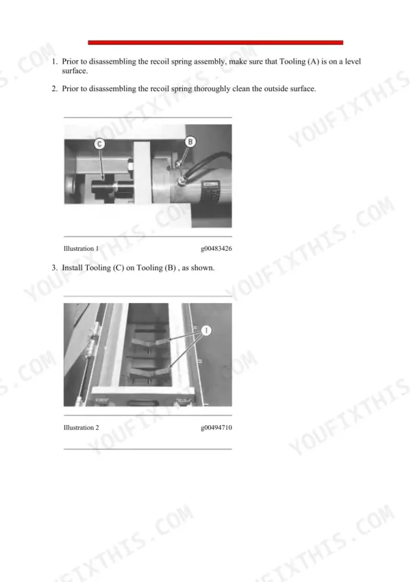
| Undercarriage & Work Tools | 5608-5761 | Hydraulic Track Adjusters - Disassemble and Install, Upper Frame and Undercarriage Frame - Separate and Connect, Front Idler, Recoil Spring |
Caterpillar 329D L, 329D LN Common Problems This Manual Covers
A CID/FMI diagnostic code keeps coming up on the D Monitor and one machine function has stopped responding.
Start at Operator Monitor - Code Troubleshooting, pages 4863 to 4999, which shows how to use the Operator Monitor to determine diagnostic codes and lists the monitor and display CID/FMI entries. Then move to Troubleshooting - Diagnostic Codes, pages 957 to 1400, for the Diagnostic Code List, the MID 039 CID/FMI entries, the electrical component and connector locations, and reading codes with Caterpillar Electronic Technician.
Manual Section: Troubleshooting - Diagnostic CodesAfter fitting a hammer or another work tool the hydraulics feel weak and slow, or the tool barely moves.
The tool is usually not set up in the machine's control system. Follow Hydraulic System - Testing, Calibration & Work Tool Setup, pages 2228 to 2731: Service Mode - Enter, Process for Setting Up the Work Tool, Work Tool Parameter - Program and Work Tool - Select. If the symptom stays after programming, Hydraulic System - Symptom & Code Troubleshooting, pages 2732 to 2945, works through circuit-by-circuit isolation and the pressure sensor CID/FMI entries.
Manual Section: Hydraulic System - Testing, Calibration & Work Tool SetupThe machine pulls to one side when tracking on flat ground.
Run the Travel on Level Ground - Test in Power Train - Final Drive & Travel, pages 5359 to 5504, which also carries travel symptom troubleshooting, Duo-Cone seal installation and final drive removal and disassembly. If the fault points at the hydraulic side, travel motor assembly is covered in Hydraulic - Pumps, Cooler, Lines & Travel Motor, pages 2946 to 3550.
Manual Section: Power Train - Final Drive & TravelThe air conditioner flashes a service code such as E11 or E13 and the cab will not cool.
Air Conditioning - Service Code Troubleshooting, pages 4666 to 4862, covers machine preparation, the visual inspection sequence, the E11 and E12 recirculation sensor faults and the E13 and E14 fresh air sensor faults. If a component has to come out, Air Conditioning & Heating - Disassembly, Assembly & Capacities, pages 5000 to 5358, covers the heating and air conditioning unit, the refrigerant compressor and the air conditioner lines.
Manual Section: Air Conditioning - Service Code TroubleshootingFrequently Asked Questions
Does the hydraulic schematic list real Caterpillar part numbers I can work from?
Yes. Page 9 carries the colour hydraulic schematic KENR6122-10, schematic part number 262-3421, drawn for the universal quick coupler attachment. The components on the circuit are labelled with their own Caterpillar part numbers: main hydraulic pump 272-6955, main control valve 259-7602, swing motor 158-8986, left and right travel motors 215-9952, travel counterbalance valves 204-2819, swing cushion valve 322-8716, swivel 234-4440, quick coupler valve 254-3080 with solenoid 258-6749, load control valves 255-5683 and 255-5680, pilot travel valve 158-8250, accumulator 164-6981, filters 188-2084, 126-2075 and 188-4140, tank 245-5141 and the pump pressure sensors 221-8859. A colour key names the circuits and a line-pattern legend separates pressure, pilot, drain, component group, attachment and air lines. p. 9
The monitor is showing a fault code and my new work tool needs programming. Where is that covered?
Two places. Troubleshooting - Diagnostic Codes, pages 957 to 1400, holds the Diagnostic Code List, the MID 039 CID/FMI entries, electrical component and connector locations, and the procedure for reading codes with Caterpillar Electronic Technician. Operator Monitor - Code Troubleshooting, pages 4863 to 4999, shows how to pull the same codes from the D Monitor in the cab. Work tool programming lives in Hydraulic System - Testing, Calibration & Work Tool Setup, pages 2228 to 2731: Service Mode - Enter, Process for Setting Up the Work Tool, Work Tool Parameter - Program, Work Tool - Select and pedal control calibration.
Why do some covers inside say 340D, 325D or C7 instead of 329D?
Caterpillar publishes service literature as separate books, and this export keeps each book's own cover. The composition was measured page by page from the media number printed in each header: 2,537 pages are the machine hydraulic and machine-systems books, titled for the 325D and 329D; 1,146 pages are the generic Caterpillar C7 engine books, which cover the engine fitted to this machine; 468 pages are the tool control system, whose covers name the 340D and 340D2; 625 pages are the machine electronic control system; 484 pages are air conditioning, including the all-products R134a book; and 379 pages are the D Monitor monitoring system. The same sharing shows on the page 9 hydraulic schematic, which is drawn for the 320D, 321D, 323D, 324D, 325D, 329D, 330D, 336D, 336D2 and 336D MHPU. A different model number on a cover means a book shared across the range, not the wrong manual.
How do I know this set matches my 329D?
Check the serial prefix. This set is for the 329D L and 329D LN with serial prefixes XDB and EBM and the Caterpillar C7 engine. The machine-specific books are titled '325D and 329D Excavators Machine System Specifications' and '325D and 329D Excavators Hydraulic System', and the electrical schematic KENR9649-03 covers the 324D and 329D excavator and the 329D MHPU with ROPS. If your serial number starts with XDB or EBM, this is the matching documentation.
5,761 pages is a lot. How is it organised, and can I get to the schematics quickly?
The schematics come first, pages 1 to 72: the colour hydraulic and electrical fold-outs, component and tap location drawings, machine component location, and the fluid power and electrical graphic symbol references you need to read them. After that the set runs system by system in labelled page ranges: basic engine testing and rebuild at pages 183 to 452, hydraulic systems operation at 1852 to 2227, control valves, relief valves and tank at 3551 to 4164, air conditioning from 4343, and undercarriage and work tools at 5608 to 5761. You navigate by page range, not by leafing.

Reviews
There are no reviews yet.