

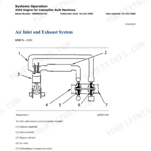
This is the factory repair library for the Cat 320C, 320C L, and 320C LN hydraulic excavators, the kind of set a dealer tech works from. It covers the engine end to end: air inlet and exhaust with turbocharger overhaul, fuel injection nozzle testing and timing checks, valve lash, compression and blowby testing, cooling and lubrication systems. On the machine side you get the full hydraulic system with pump regulation and travel motor testing, final drives with duo-cone seal installation, undercarriage and track adjuster service, swing gear, boom removal, and quick coupler work. Electrical coverage includes wiring schematics, CID/FMI code troubleshooting, and ECM flash programming; note that roughly 455 pages of the electrical section document EquipmentManager and Product Link dealer telematics software rather than machine repair.
Other editions of this manual
What's Inside This Caterpillar 320C Repair Manual
| System | Pages | Key Topics |
|---|---|---|
| Air Inlet and Exhaust System | 1-55 | Turbocharger Inspection and Overhaul, Exhaust Manifold Removal and Installation, Inlet Manifold Service, Air Cleaner Removal, Muffler Removal |
| Basic Engine | 56-384 | Finding Top Center Position, Fuel Injection Nozzle Testing, Crankcase Blowby Pressure Testing, Compression Testing, Valve Lash Inspection and Adjustment, Valve Guide Inspection |
| Cooling System | 385-470 | Overheating Checks, Cooling System Inspection and Pressure Testing, Engine Oil Cooler Service, Water Temperature Regulator Testing |
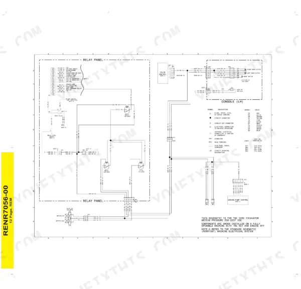
| Electrical Systems Operation, Testing and Controls | 471-625 | Power Circuit, Start and Stop Circuit, Charging Circuit, Engine and Pump Speed Regulation, Automatic Engine Control, Switches and Sensors, Solenoid Valves |
| Electrical - EquipmentManager and Product Link (Dealer Software, Not Machine Repair) | 626-1080 | Manage Users and Equipment Groups, Product Link Installation and Subscriptions, Planned and Major Repair Tracking, Asset Watch and Geographic Fencing, Health Watch and Fuel Reports |
| Electrical - Troubleshooting, Wiring Harness and System Schematics | 1081-1774 | Alternator and Charging System Testing, Wiring Harness Open and Short Circuit Testing, Diagnostic Trouble Code Troubleshooting, Electronic Control Module Replace and Flash Program, System Schematics |
| Engine Arrangement | 1775-1804 | Engine Design, Engine Speed Performance Testing, Engine Troubleshooting |
| Frame and Body | 1805-1904 | Travel Motor Fasteners and Guard, Hood Removal and Installation, Swing Gear and Bearing Service |
| Fuel System | 1905-2246 | Governor Actuator Control, Air in Fuel Testing, Fuel Injection Nozzle Testing, Fuel Injection Timing Check, Fuel Quality Testing |
| Hydraulic System | 2247-4386 | Main and Pilot Hydraulic System Description, Main Control Valve and Pump Regulation, Boom and Stick Cylinder Lines, Travel Motor Testing, Diagnostic Trouble Codes, Gear Pump Disassembly, Counterbalance and Flow Divider Valves |
| Implements | 4387-4506 | SmartBoom Hydraulic System, Boom and Fore Boom and Stub Boom Service, Boom Removal |
| Lubrication System | 4507-4578 | Engine Oil Pressure and Pump Testing, Excessive Oil Consumption Diagnosis, Crankcase Breather Service |
| Machine Arrangement | 4579-4591 | Service Intervals, Heating and Air Conditioning Service Publications |
| Operator Station | 4592-5566 | Air Conditioning System Schematic, Refrigerant Receiver-Dryer and Recovery, Cab Sensors, Coolant Temperature Sensor |
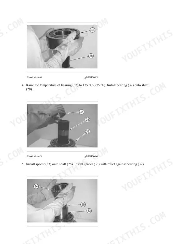
| Power Train | 5567-5661 | Final Drive Testing and Disassembly, Duo-Cone Seal Installation, Travel on Level Ground Testing |
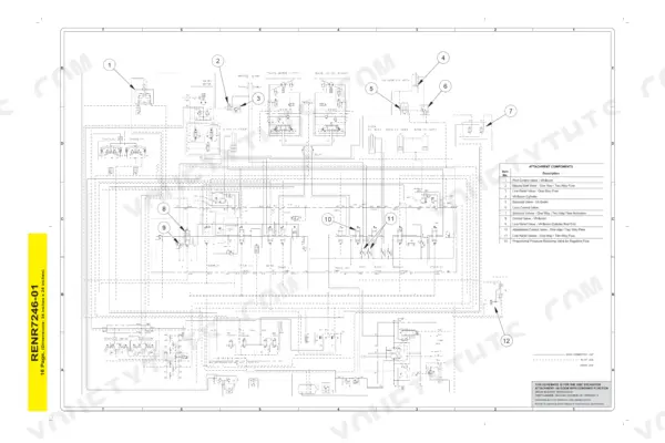
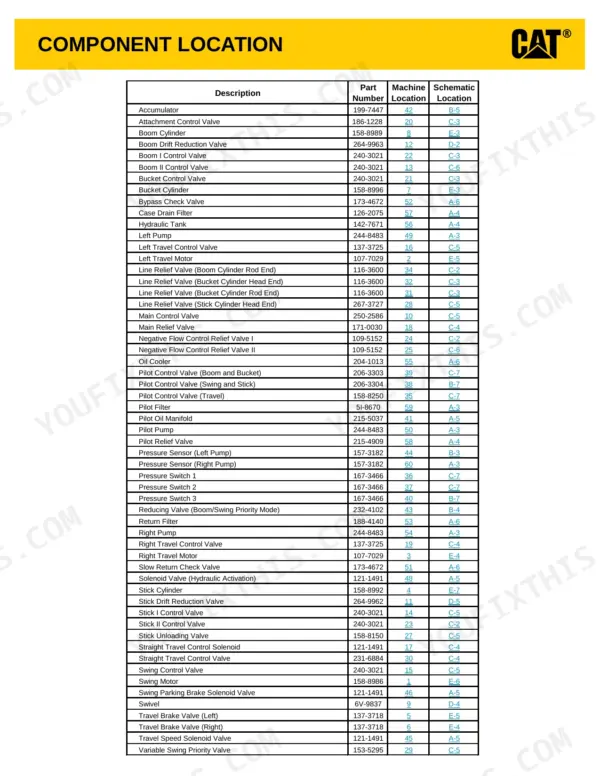
| Schematic | 5662-5751 | Hydraulic Attachment Schematics, Electrical Harness and Wire Schematic Symbols, Component Location Diagrams |
| Service Equipment and Supplies | 5752-5809 | Cab Pressurization and Filtration, Refrigerant Manifold Gauge Set Service |
| Torque Specifications | 5810-5858 | Ground Engaging Tool Fastener Torque, Standard Bolt Torque, Straight Thread O-Ring Fitting Torque |
| Undercarriage | 5859-5926 | Front Idler and Recoil Spring Service, Hydraulic Track Adjuster Disassembly |
| Work Tools Arrangement | 5927-5932 | Medium Pressure Hydraulic System |
| Work Tools | 5933-5954 | Bucket Adjuster and Removal, Hydraulic and Mechanical Quick Coupler Service |
Quick Reference Specifications
| Specification | Value | Page |
|---|---|---|
| Exhaust manifold nut torque (3066 Engine) | 18 +/- 4 N.m (13 +/- 3 lb ft) | p. 20 |
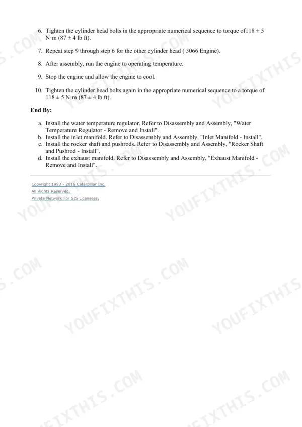
| Cylinder head bolt torque (3066 Engine) | 118 +/- 5 N.m (87 +/- 4 lb ft) | p. 244 |
| Alternator retaining nut torque | 132 to 162 N.m (95 to 120 lb ft) | p. 1717 |
| Fuel injection line nut torque | 26.5 to 32.4 N.m (20 to 24 lb ft) | p. 70 |
| Swing relief valve pressure setting | 26000 +/- 980 kPa (3750 +/- 140 psi) | p. 2645 |
| Work tool relief valve pressure setting | 20600 +/- 1500 kPa (2990 +/- 220 psi) | p. 2782 |
| Main relief valve pressure setting | 34300 +/- 490 kPa (4975 +/- 71 psi) | p. 3884 |
| Line relief valve pressure setting (boom, stick, bucket) | 36300 +/- 490 kPa (5265 +/- 71 psi) | p. 3884 |
| Negative flow control pressure (drive pump shim adjustment) | 2350 kPa (340 psi); 0.1 mm shim change = 3 L/min (0.8 US gpm) flow change | p. 2703 |
| Hydraulic oil test temperature for main relief valve check | 55 +/- 5 C (131 +/- 9 F) | p. 2617 |
| Accumulator charge pressure at -25 C (-13 F) | 1490 kPa (216 psi) | p. 2606 |
| Accumulator charge pressure at -10 C (14 F) | 1580 kPa (229 psi) | p. 2606 |
Caterpillar 320C Common Problems This Manual Covers
Swing is completely inoperable and the monitor shows a fault
Follow Swing Is Inoperable - Troubleshoot - CID 374 on page 1292. The procedure isolates the cause between a swing brake solenoid issue, a controller problem, a hydraulic system problem, or a harness and wiring fault before you start swapping parts.
Manual Section: Swing Is Inoperable - Troubleshoot - CID 374 p. 1292Machine controller is dead with no power supply
Page 1140 sends you to Testing And Adjusting, No Power Supply to Controller - Troubleshoot. You work the diagnostic flowcharts for your specific machine model step by step, checking the power path until the dead leg shows itself.
Manual Section: No Power Supply to Controller - Troubleshoot p. 1140Monitor keeps flashing the high hydraulic oil temperature warning
Start with the CID 600 procedure on page 4758. One of its first checks is that the hydraulic oil type displayed on the monitor actually matches the oil in the machine, since a mismatch there can drive the warning before you chase coolers.
Manual Section: Warning "Hydraulic Oil Temperature Is High" Is Displayed - Troubleshoot - CID 600 p. 4758Low idle switch has no effect on engine speed
Use Low Idle Switch Does Not Work - Troubleshoot on page 1216. The manual gives you a troubleshooting flowchart in Illustration 1 to diagnose the issue, so you trace the circuit in order instead of guessing between the switch, wiring, and controller.
Manual Section: Low Idle Switch Does Not Work - Troubleshoot p. 1216Frequently Asked Questions
What is the swing relief valve pressure setting on a 320C?
The swing system testing procedure on page 2645 gives the number directly: the pressure setting of the swing relief valve is 26000 +/- 980 kPa (3750 +/- 140 psi). If your reading at the pressure tap is not within that range, the manual walks you through adjusting the swing relief valve. p. 2645
My engine speed dial does nothing. What does the manual say to check?
There is a dedicated procedure, Engine Speed Dial Does Not Work - Troubleshoot - CID 586, on page 1207. It walks you through the possible causes: an engine problem, a faulty speed dial itself, a harness problem, or an open circuit / poor contact at the body ground terminal. p. 1207
How tight do the fuel injection line nuts go?
Page 70, in the Fuel Injection Lines section, says to use a torque wrench and tighten the nuts of the fuel injection lines to 26.5 to 32.4 N.m (20 to 24 lb ft). Guessing on these nuts is how you end up with cracked lines or diesel misting on a hot engine. p. 70
What is the main relief valve pressure setting on the hydraulic system?
Page 3884 lists it plainly: the main relief valve pressure setting is 34300 +/- 490 kPa (4975 +/- 71 psi), and the line relief valve for the boom, stick, and bucket is set slightly higher at 36300 +/- 490 kPa (5265 +/- 71 psi). Knowing both numbers keeps you from adjusting the wrong valve. p. 3884
Any guidance on torque wrench technique, or just the numbers?
Both. The General Information part of the Torque Specifications section, page 5811, spells out technique: always use a smooth pull on the wrench, never jerk it, and do not use adapters that change the length of the torque wrench, since that throws the reading off. p. 5811
Reviews
There are no reviews yet.