
This is the full Caterpillar factory repair library for the 924G and 924GZ wheel loaders, 1998 to 2006: Systems Operation, Testing and Adjusting, and Disassembly and Assembly in one download. Twenty section PDFs, 3557 pages, covering everything from the load-sensing hydraulic pump to the operator station. These are the same procedures a Cat dealer tech follows, with the actual numbers you need on the gauge: pump cutoff at 25850 kPa (3750 psi), standby at 2000 kPa (290 psi), pilot system at 2600 kPa (375 psi). Dedicated Torque Specifications and Schematics sections mean you are not flipping through chapters hunting for one bolt value or one wire color. If you keep one of these loaders earning, this is the book.
Other edition of this manual
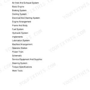
What's Inside This Caterpillar 924G/924GZ Repair Manual
| System | Pages | Key Topics |
|---|---|---|
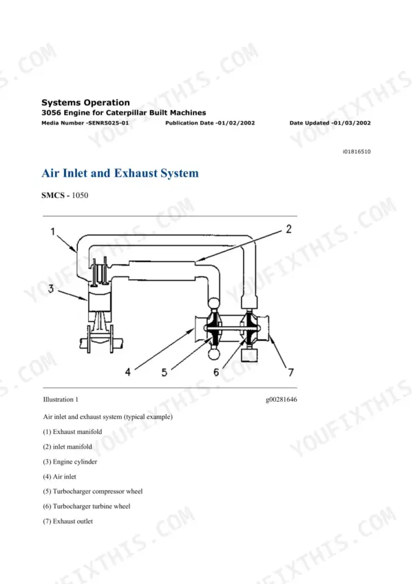
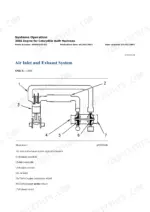
| Air Inlet and Exhaust System | 3-59 | Turbocharger, Air Cleaner, Exhaust |
| Basic Engine | 60-376 | Engine Disassembly and Assembly, Head, Block, Crankshaft, Bearings |
| Braking System | 377-506 | Service and Park Brakes, Valves, Accumulators, Brake Tests |
| Cooling System | 507-588 | Radiator, Water Pump, Thermostat, Fan Drive Motor Test |
| Electrical and Starting System | 589-1032 | Alternator, Starter, Batteries, Harnesses, Circuit Tests |
| Engine Arrangement | 1033-1256 | Engine Mounting and Arrangement |
| Frame and Body | 1257-1327 | Frame, Covers, Guards, Counterweight |
| Fuel System | 1328-1467 | Injection Pump, Injectors, Filters, Fuel Testing |
| Hydraulic System | 1468-2013 | Load-Sensing Pump Cutoff, Standby and Margin Pressure, Pilot System, Line Relief Test and Adjust, Cylinders |
| Implements | 2014-2077 | Loader Linkage, Bucket, Quick Coupler |
| Lubrication System | 2078-2108 | Oil Pump, Filters, Lubrication Routing |
| Machine Arrangement | 2109-2139 | Overall Machine Arrangement |
| Operator Station | 2140-2663 | Cab, Controls, Monitor, HVAC |
| Power Train | 2664-3289 | Transmission Pressure Test and Adjust, Selector and Pressure Control Valve, Torque Converter, Axles |
| Service Equipment and Supplies | 3290-3337 | Special Tools, Service Supplies |
| Steering System | 3338-3465 | Steering Pump, Valve, Cylinders, Pressure Checks |
| Work Tools | 3466-3490 | Bucket and Attachment Service |
| Torque Specifications | 3491-3538 | Standard Metric and Inch Tightening Torques, Fitting and Hose Torques |
| Schematics | 3539-3557 | Hydraulic and Electrical Schematics |
Quick Reference Specifications
| Specification | Value | Page |
|---|---|---|
| Pump Cutoff Pressure | 25850 ± 345 kPa (3750 ± 50 psi) | p. 1579 |
| Standby Pressure | 2000 ± 200 kPa (290 ± 30 psi) | p. 1581 |
| Margin Pressure | 2000 ± 100 kPa (290 ± 15 psi) | p. 1581 |
| Maximum Case Drain Pressure | 207 kPa (30 psi) | p. 1583 |
| Pump Cutoff Pressure (Adjustment Target) | 30000 kPa (4350.0 psi) | p. 1587 |
| Signal Oil Pressure | 23750 ± 350 kPa (3450.0 ± 50.0 psi) | p. 1588 |
| Maximum Signal Oil Pressure | 23750 ± 350 kPa (3450.0 ± 50.0 psi) | p. 1591 |
| Maximum Pump Output Pressure | 25850 ± 350 kPa (3750.0 ± 50.0 psi) | p. 1591 |
| Maximum Standby Pressure | 4300 ± 170 kPa (625 ± 25 psi) | p. 1597 |
| Pilot System Pressure | 2600 ± 170 kPa (375.0 ± 25.0 psi) | p. 1598 |
| Line Relief Valve: Tilt Head End | 12300 ± 170 kPa (1785 ± 25 psi) | p. 1603 |
| Line Relief Valve: Tilt Rod End | 27579 ± 345 kPa (4000 ± 50 psi) | p. 1603 |
| Line Relief Valve: Auxiliary Head End | 27579 kPa (4000 psi) | p. 1603 |
| Line Relief Valve: Auxiliary Rod End | 27579 kPa (4000 psi) | p. 1603 |
| Locknut Adjustment Torque | 4 ± 1 N·m (3 ± 1 lb ft) | p. 1605 |
Caterpillar 924G/924GZ Common Problems This Manual Covers
Bucket and lift feel slow or weak, especially under load
Before condemning the pump, put a gauge on it. The Testing and Adjusting procedures in the Hydraulic System section walk you through checking standby pressure (2000 ± 200 kPa / 290 ± 30 psi), margin pressure and pump cutoff (25850 ± 345 kPa / 3750 ± 50 psi), then adjusting the load-sensing compensator to spec.
Manual Section: Hydraulic System p. 1468Bucket drifts or dumps on its own with the lever centered
Usually a line relief valve or cylinder seal, not the control valve. The Hydraulic System section gives the test procedure and the settings to verify: tilt head end relief at 12300 ± 170 kPa (1785 ± 25 psi) and tilt rod end at 27579 ± 345 kPa (4000 ± 50 psi), plus cylinder drift checks that separate a relief problem from a piston seal problem.
Manual Section: Hydraulic System p. 1468Suspected worn hydraulic pump, deciding between adjust and rebuild
The case drain flow and pressure test settles it. The Hydraulic System section specifies maximum case drain pressure at 207 kPa (30 psi); measure above that and internal leakage is eating your flow. The Disassembly and Assembly procedures then cover pump removal and rebuild step by step.
Manual Section: Hydraulic System p. 1468Harsh shifts, slipping under load, or the loader creeping in gear
Start with transmission clutch pressure tests before pulling anything apart. The Power Train section covers Systems Operation so you understand how the clutches engage, Testing and Adjusting for pressure checks at the test ports, and full Disassembly and Assembly if a clutch pack actually needs to come out.
Manual Section: Power Train p. 2664Frequently Asked Questions
Does this manual cover my machine's serial number?
Check the serial prefix on your frame plate against the ones listed on this page before you buy. Cat split the 924G/924GZ documentation by serial range, and if your machine's prefix is DDA, RBB, WMB, DFZ, RTA or WGX, it is covered by our companion 924G listing instead of this one. Same model name, different books.
How do I reset the error codes or warning light on a 924G?
Honest answer: on a machine of this era there is no laptop plug-in and no code-clearing menu. Most warnings come straight from a pressure switch, temperature sender or level sensor, so the light stays on until you fix what tripped it. The Testing and Adjusting procedures tell you which switch or circuit to check, and the Electrical And Starting System section plus the Schematics section let you trace the wire to the actual cause instead of guessing.
Are the real hydraulic pressure specs in here, with tolerances?
Yes, the actual test values, not vague ranges. Pump cutoff 25850 ± 345 kPa (3750 ± 50 psi), standby 2000 ± 200 kPa (290 ± 30 psi), margin 2000 ± 100 kPa, pilot system 2600 ± 170 kPa (375 ± 25 psi), signal oil 23750 ± 350 kPa (3450 ± 50 psi), line relief values for the tilt and auxiliary circuits, plus where to tee in the gauge and how to adjust each one. p. 1576
Does it include torque specs and wiring/hydraulic schematics?
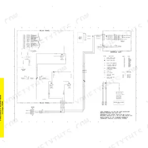
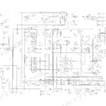
Both get their own dedicated sections. Torque Specifications is a standalone PDF so you can keep it open on a phone while your hands are on the wrench, and the Schematics section carries the electrical and hydraulic diagrams you need for tracing a dead circuit or a stuck valve.
What format is it, and can I print just what I need?
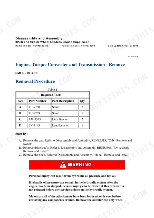
Twenty separate PDF files totaling 3557 pages, organized by system: Hydraulic System, Power Train, Braking System, Steering System, Fuel System, Cooling System and so on. Because each system is its own file, you can print the 30 pages for the job in front of you instead of wrestling a full binder into the cab.
Reviews
There are no reviews yet.