
This is the factory repair manual for the Caterpillar 924G and 924Gz wheel loaders (serial prefixes DDA, RBB and WMB, with DBT and WAC in the applicability list). It covers the 3056E engine end to end: valve lash adjustment, compression testing, finding top center on the No. 1 piston, fuel injection nozzle testing and front gear group timing. Hydraulics come with real test numbers, not guesswork - pump cutoff at 25,850 kPa (3750 psi), standby at 1960 kPa (290 psi). Braking, steering, power train, frame separation, quick coupler work and the machine-specific electrical schematic (media RENR6432-01) are all in here, plus ECM self-diagnostics and Cat Electronic Service Tool procedures for chasing indicator lamp faults.
Other edition of this manual
What's Inside This Caterpillar 924G, 924Gz Repair Manual
| System | Pages | Key Topics |
|---|---|---|
| Air Inlet and Exhaust System | 1-76 | Air Inlet and Exhaust System - Inspect, Turbocharger - Inspect, Engine Has Early Wear, Excessive Black Smoke, Intake Air Temperature Is Too High |
| Basic Engine | 77-455 | Finding Top Center Position for No. 1 Piston, Fuel Injection Nozzle - Test, Gear Group (Front) - Time, Compression - Test, Engine Valve Lash - InspectAdjust |
| Braking System | 456-621 | General Information (Braking), Gear Pump (Braking and Hydraulic Fan), Brake Accumulator, Brake Control Valve (Service), Parking Brake |
| Cooling System | 622-755 | Cooling System - Check, Cooling System - Inspect, Cooling System - Test, Engine Oil Cooler - Inspect, Water Temperature Regulator - Test |
| Electrical and Starting System, Systems Operation | 756-890 | Electrical System, Electronic Control System, Coupler Control, Pressure Switch (Refrigerant) |
| Electrical and Starting System, Testing and Adjusting | 891-1006 | Air Inlet Heater - Test, Alternator - Test, Battery - Test, Belt Tension Chart, Charging System - Test, Electric Starting System - Test |
| Electrical and Starting System, Troubleshooting, Specifications & Disassembly | 1007-1775 | System Overview, Glossary, Electronic Service Tools, Indicator Lamps, Replacing the ECM, Self-Diagnostics |
| Engine Arrangement | 1776-1810 | Engine Speed - Check, Engine Design, Steering Frame Lock - Separate and Connect, System Pressure - Release, Engine - Remove |
| Frame and Body | 1811-1872 | Steering Frame Lock - Separate and Connect, Loader Frame and Rear Frame - Separate, Loader Frame and Rear Frame - Connect, Power Train Guard (Transmission) - Remove and Install, Articulated Hitch |
| Fuel System | 1873-2029 | Fuel Injection, Fuel System - Inspect, Air in Fuel - Test, Fuel Injection Nozzle - Test, Fuel Injection Timing - Check |
| Hydraulic System | 2030-2572 | Oil Filter (Hydraulic), Hydraulic Oil Cooler, Piston Pump (Steering and Pilot), Piston Pump (Implement), Pilot Hydraulic System |
| Implements | 2573-2630 | Work Tool Control, Tilt Lever (Front) and Tilt Link (Front) - Remove, Tilt Lever (Front) and Tilt Link (Front) - Install, Tilt Lever (Rear) - Remove, Tilt Lever (Rear) - Install |
| Lubrication System | 2631-2686 | Coolant in Engine Oil, Engine Oil Pump - Inspect, Excessive Engine Oil Consumption - Inspect, Increased Engine Oil Temperature - Inspect, Excessive Engine Oil Consumption |
| Machine Arrangement | 2687-2705 | Service Intervals, Heating and Air Conditioning Service Publications, Symptom Troubleshooting, Emerging Symptom Information |
| Operator Station [] | 2706-3241 | Operator Station, Power Sources, Identifying the Refrigerant, Identifying the Air Conditioning System, Identifying the Heating System, Refrigerant Expansion Valve System |
| Power Train [] | 3242-4084 | Power Train, Service Brakes, Location of Electrical Components, Location of Hydraulic Components, Electrical Input Components |
| Schematic | 4085-4162 | RENR6432-01, Cover Page, Page 1 of 2, Page 2 of 2 |
| Service Equipment and Supplies | 4163-4207 | Cab Pressurization and Filtration System, Oil Filter (Power Train), Manifold Gauge Set (Refrigerant) - Install, Manifold Gauge Set (Refrigerant) - Remove, Heating and Air Conditioning Service Publications |
| Steering System | 4208-4347 | General Information (Steering), Piston Pump (Steering and Pilot), Metering Pump (HMU), Secondary Steering System - If Equipped, Secondary Steering Pump and Electric Motor |
| Torque Specifications | 4348-4396 | Metric (ISO) Fasteners, English (SAE) Fasteners, Ground Engaging Tool (G.E.T.) Fasteners, Installation of Fittings, Straight Thread O-Ring Fittings |
| Work Tools | 4397-4418 | Coupler Control, Bucket - Remove, Bucket - Install, Quick Coupler - Remove, Quick Coupler - Install |
Quick Reference Specifications
| Specification | Value | Page |
|---|---|---|
| Hydraulic pump cutoff pressure | 25,850 ± 350 kPa (3750 ± 50 psi) | p. 2148 |
| Maximum signal oil pressure | 23,750 ± 350 kPa (3450 ± 50 psi) | p. 2150 |
| Hydraulic pump standby pressure | 1960 ± 240 kPa (290 ± 30 psi) | p. 2151 |
| Maximum pump case drain pressure | 207 kPa (30 psi) | p. 2152 |
| Relief valve pressure setting | 27,600 ± 350 kPa (4000 ± 50 psi) | p. 2165 |
Caterpillar 924G, 924Gz Common Problems This Manual Covers
Excessive black smoke and the engine feels down on power
Start in the Air Inlet And Exhaust System section, which has a dedicated Excessive Black Smoke troubleshooting path. Run the Air Inlet and Exhaust System - Inspect and Turbocharger - Inspect procedures first to rule out a plugged filter, boost leak or tired turbo, then move to the Fuel System section for nozzle testing and injection timing checks.
Manual Section: Air Inlet And Exhaust System p. 76Milky oil or coolant showing up in the crankcase
The Lubrication System section has a Coolant in Engine Oil procedure that walks the likely paths coolant takes into the pan. Work it alongside the Cooling System - Test and Engine Oil Cooler - Inspect procedures to pin down whether the cooler core, a gasket or a liner seal is the leak before you tear anything down.
Manual Section: Lubrication System p. 622Hydraulics slow and weak under load, bucket struggles to break out
Use the Hydraulic System section to test the implement piston pump against the published numbers: standby pressure of 1960 ± 240 kPa (290 ± 30 psi), cutoff at 25,850 ± 350 kPa (3750 ± 50 psi), and case drain no higher than 207 kPa (30 psi). High case drain flow with low cutoff points straight at a worn pump rather than a valve problem.
Manual Section: Hydraulic System p. 2148Brakes dragging, weak pedal, or the parking brake will not release
The Braking System section covers the whole circuit: the Gear Pump (Braking and Hydraulic Fan) that supplies it, Brake Accumulator testing to confirm charge pressure, the Brake Control Valve (Service) procedures for pedal and apply problems, and the Parking Brake procedures for a stuck or slipping park brake. Check accumulator charge before condemning any valve.
Manual Section: Braking System p. 456Frequently Asked Questions
How do I read and reset fault codes on a Cat 924G?
This loader is Cat SIS era, not OBD - there is no generic port for a parts store scanner. The ECM flags faults through indicator lamps, and the Electrical And Starting System troubleshooting section walks you through Self-Diagnostics, reading the lamps, hooking up the Electronic Service Tools and what each indicator means. Most codes stop returning once the underlying fault is actually fixed, and the manual also covers Replacing the ECM if the module itself is bad. p. 1011
What hydraulic pressures should I be testing against?
The Hydraulic System section gives you the real numbers: pump cutoff at 25,850 ± 350 kPa (3750 ± 50 psi), maximum signal oil pressure at 23,750 ± 350 kPa (3450 ± 50 psi), standby at 1960 ± 240 kPa (290 ± 30 psi), relief valve setting at 27,600 ± 350 kPa (4000 ± 50 psi), and a maximum pump case drain of 207 kPa (30 psi). Case drain above that number is your early warning on a wearing piston pump. p. 2148
Does the manual include torque specs?
Yes, but know what kind. The Torque Specifications section carries the standard fastener chart — metric and SAE values by bolt size, shared across Caterpillar equipment rather than unique to the 924G — while the machine-specific tightening values sit inside each system's own disassembly and assembly procedures, called out step by step where the fastener is fitted. p. 4348
Will this manual match my machine?
It covers 924G and 924Gz wheel loaders from the 1998 to 2005 production run, serial prefixes DDA, RBB and WMB, with DBT and WAC also listed in the applicability block. Check the serial plate on the frame before you buy - the prefix is the first three characters. p. 4401
Is the full wiring schematic included?
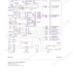
Yes, the machine-specific electrical schematic (media RENR6432-01) is included as its own section, both sheets plus the cover page. Pair it with the Power Train section, which maps the physical location of electrical and hydraulic components on the machine, and you can actually trace a circuit instead of guessing where a connector hides. p. 4093
Reviews
There are no reviews yet.