
This is the factory service compilation Cat dealers used on the 236, 246 and 248 skid steers - bound from the separate engine, interlock ECM, hydraulic, power train and machine systems publications, so it also carries the shared sections for the wider 216 to 262 loader family. You get foldout electrical and hydraulic schematics (the 248 has its own hydraulic sheet, RENR2890), full engine work from compression testing (2450 to 2950 kPa at 250 rpm) to valve lash (0.35 mm cold), the hydrostatic pumps and motors, tandem drive and axles, pilot hydraulics with actual cylinder speed test times, the seat and armrest interlock system, fuel injection testing, and torque specs down to face seal fittings. Remove and install procedures and troubleshooting throughout.
Other edition of this manual
What's Inside This Caterpillar 236, 246, 248 Repair Manual
| System | Pages | Key Topics |
|---|---|---|
| Schematic | 1-26 | Electrical System Schematics, Hydraulic System Schematics, Component Location, Machine View |
| Air Inlet and Exhaust System | 27-51 | Turbocharger, Exhaust Manifold, Inlet Manifold, Muffler |
| Basic Engine | 52-350 | Finding Top Center Position, Compression Test, Engine Valve Lash Inspect and Adjust, Connecting Rod Bearings, Valve Guide Inspect, Gear Group Timing |
| Cooling System | 351-465 | Water Temperature Regulator Test, Radiator and Hydraulic Oil Cooler, Engine Oil Cooler, Fan Motor, Overheating Checks |
| Electrical and Starting System | 466-1579 | Electronic Control Module, Engine Start Interlock, Hydrostatic System Interlock, Work Tool Interlock, Solenoid Valve, Relays, Diagnostic Operation |
| Engine Arrangement | 1580-1754 | Engine Design, Engine Remove and Install, Troubleshooting |
| Frame and Body | 1755-1780 | Loader Frame, Engine Enclosure Remove and Install |
| Fuel System | 1781-1910 | Governor Control, Fuel Injection Nozzle Test, Fuel Injection Timing Check, Fuel Setting Adjust, Air in Fuel Test, Fuel System Prime |
| Hydraulic System | 1911-2454 | Pilot Hydraulic System, Pilot Valve Joystick, Bank Valve, Interlock Manifold Valve, Diverter Valve |
| Implements | 2455-2511 | Work Tool Control, Lift Arms Remove and Install |
| Lubrication System | 2512-2549 | Engine Oil Pump Inspect, Engine Oil Filter Base, Engine Oil Relief Valve, Crankcase Breather, Excessive Oil Consumption Checks |
| Machine Arrangement | 2550-2561 | Service Intervals, Heating and Air Conditioning Service |
| Operator Station | 2562-3182 | Switches, Indicators, Sensors, Air Conditioning System, Refrigerant Identification, Pilot Valve Joystick |
| Power Train | 3183-3410 | Piston Pump Hydrostatic, Piston Motor Hydrostatic, Tandem Drive, Axle, Hydrostatic System Troubleshooting |
| Service Equipment and Supplies | 3411-3429 | Cab Pressurization and Filtration, Manifold Gauge Set, Fuel Filter Base, Required Tools |
| Torque Specifications | 3430-3477 | Metric Fasteners, Inch Fasteners, Ground Engaging Tool Fasteners, Fitting Installation, Face Seal Fittings |
| Work Tools | 3478-3486 | Quick Coupler, Coupler Cylinder, Quick Coupler Remove and Install |
Quick Reference Specifications
| Specification | Value | Page |
|---|---|---|
| Cylinder Compression Pressure | 2450 to 2950 kPa at 250 rpm | p. 71 |
| Max Cylinder Compression Variation Between Cylinders | 350 kPa (51 psi) | p. 71 |
| Valve Lash Setting, Cold Engine (Inlet and Exhaust) | 0.35 mm (0.014 inch) | p. 74 |
| Timing Gear Backlash, Max Allowable | 0.25 mm (0.010 inch) | p. 68 |
| Fuel Injection Nozzle Back-Leakage Time | 5 to 45 seconds | p. 64 |
| Hydraulic Oil Test Temperature | 50 ± 10°C (122 ± 18°F) | p. 2055 |
| Lift Cylinder Speed, Raise (236/246) | 2.7 ± 0.2 seconds | p. 2056 |
| Lift Cylinder Speed, Lower (236/246) | 2.7 ± 0.2 seconds | p. 2056 |
| Lift Cylinder Speed, Float (236/246) | 2.8 ± 0.2 seconds | p. 2056 |
| Tilt Cylinder Speed, Tilt Forward (236/246) | 2.1 ± 0.2 seconds | p. 2057 |
| Tilt Cylinder Speed, Tilt Back (236/246) | 1.6 ± 0.2 seconds | p. 2057 |
| Charge Circuit Max Fill Pressure | do not exceed 4000 kPa (580 psi) | p. 2075 |
| Work Tool Main Relief Valve Adjustment (per 1.5 turns clockwise) | +13500 kPa (1960 psi) | p. 2095 |
| Engine Speed, Low Idle (248) | 1000 ± 50 rpm | p. 3233 |
| Engine Speed, High Idle (248) | 2900 ± 50 rpm | p. 3233 |
| Engine Stall Speed (228 and 248) | 2200 ± 500 rpm | p. 3244 |
| MA Pressure, Stall Test (228 and 248) | 38200 ± 2000 kPa (5540 ± 290 psi) | p. 3244 |
| Brake Pressure, Disengaged (228 and 248) | 2900 ± 100 kPa (420 ± 14 psi) | p. 3249 |
| Max Displacement Adjustment Locknut Torque | 22 N·m (16 lb ft) | p. 3250 |
Caterpillar 236, 246, 248 Common Problems This Manual Covers
Machine will not start, or starts and immediately locks out the drive and work tool
Work the Engine Start Interlock procedures in the Electrical and Starting System section. The interlock ECM reads the seat, armrest and parking brake switches and blocks starting until the seat is occupied and the armrest is down. The manual walks each switch, relay and circuit test before you condemn a starter or harness.
Manual Section: Electrical and Starting System - Engine Start Interlock / Hydrostatic System Interlock p. 466Loader hydraulics are weak, slow or erratic
Warm the oil to 50 +/- 10 C and run the cylinder speed checks in the Hydraulic System section - lift raise on a 236/246 should take 2.7 +/- 0.2 seconds. Slow times send you into the pilot hydraulic system and bank valve tests, and the relief valve adjustment rate is printed so you are not guessing at the screw.
Manual Section: Hydraulic System - Pilot Hydraulic System / Bank Valve p. 2051Engine overheats under load
Follow the Overheating Checks in the Cooling System section. The radiator and hydraulic oil cooler sit stacked on these machines, so debris packed between the cores is the usual cause. The section also covers the water temperature regulator test and fan motor checks, so you rule things out in order instead of throwing parts at it.
Manual Section: Cooling System - Overheating Checks / Radiator and Hydraulic Oil Cooler p. 351Engine cranks but will not fire, or dies after a fuel filter change
Go through the Fuel System section in order: prime the system, run the Air in Fuel Test, then test the injection nozzles - back-leakage should take 5 to 45 seconds. The fuel injection timing check and fuel setting adjustment are covered too, and the interlock must be satisfied before the engine will crank at all.
Manual Section: Fuel System - Fuel System Prime / Air in Fuel Test p. 1781Frequently Asked Questions
My machine cranks and runs but the drive and loader hydraulics are dead. Is something broken?
Usually not. These machines have an interlock ECM that reads the seat switch, armrest switch and parking brake switch. Leave the seat or raise the armrest and it kills the hydrostatic drive, disables the work tool hydraulics and sets the parking brake by design. The Electrical and Starting System section shows how the interlock works and how to test each switch and circuit when one of them fails and locks you out for real. p. 2051
Does this manual cover fault codes, and do I need Cat ET software?
The base machine has no digital fault code display. When the interlock ECM sees a circuit fault it flashes the parking brake or armrest indicator, and the manual's Diagnostic Operation coverage tells you what that flashing means and where to test. Only the auxiliary hydraulic ECM, if your machine has one, puts out CID-FMI flash codes over the Cat Data Link read with Cat ET. For everything else you diagnose with the schematics and a meter, which the manual is built for. p. 466
It cranks but will not start. Will this manual actually help me find why?
Yes, and it makes you check the cheap stuff first. The Fuel System section has the Fuel System Prime procedure, the Air in Fuel Test, the fuel injection timing check and the nozzle test with a real pass spec - back-leakage time of 5 to 45 seconds. The Electrical and Starting System section covers the start interlock, relays and solenoid valve, because a seat switch or blown fuse stops these machines as often as a fuel problem does. p. 1781
Are full wiring and hydraulic schematics included?
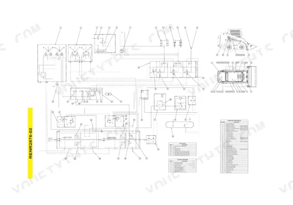
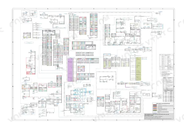
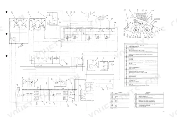
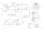
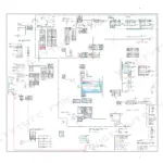
Yes. There is a foldout electrical schematic covering the 216 through 248 machines, a hydraulic schematic foldout for the 216, 226, 236 and 246, and a separate hydraulic schematic for the 248. The Schematic section also has component location drawings and machine views, so you can find the actual relay or valve on the machine instead of just on paper. p. 8
Can I test and adjust hydraulic performance myself, or is that dealer-only?
You can do it with a gauge set. The manual gives the test conditions - hydraulic oil at 50 +/- 10 C - and hard numbers like lift raise and lower times of 2.7 +/- 0.2 seconds on the 236/246. It tells you the work tool main relief changes about 13500 kPa per 1.5 turns of the screw, and warns you not to exceed 4000 kPa when filling the charge circuit. The Service Equipment and Supplies section lists the required tools. p. 2055


Reviews
There are no reviews yet.