
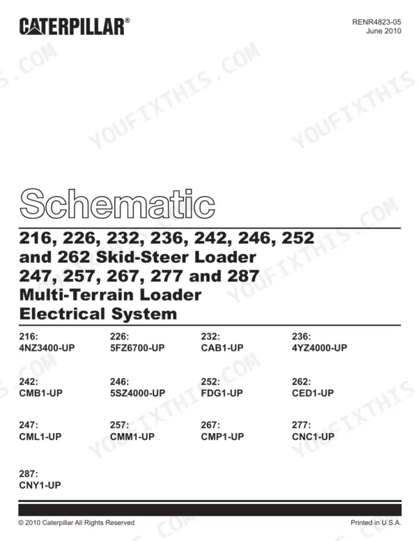
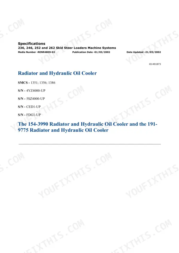
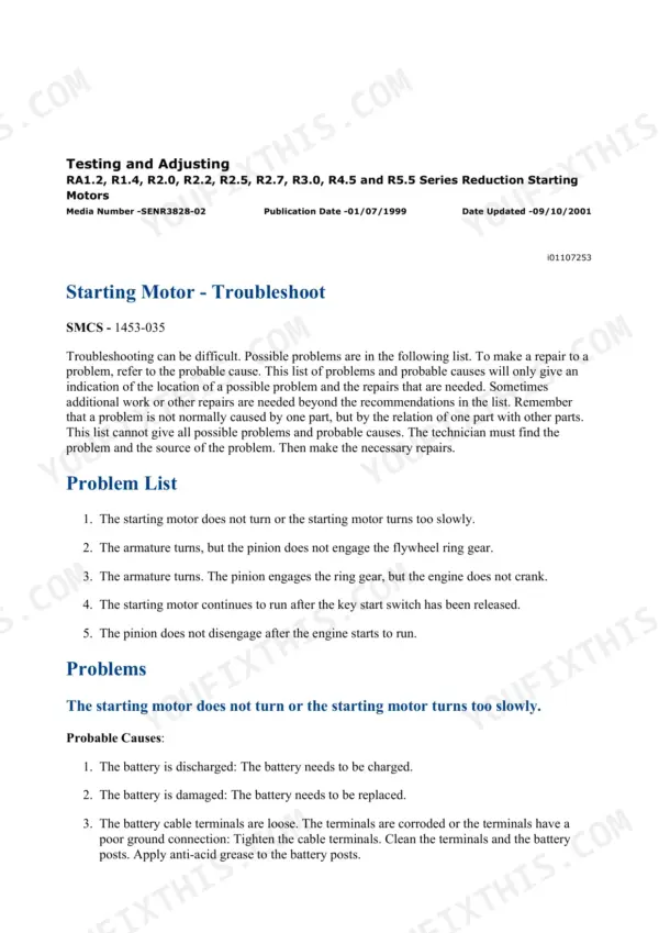
Factory Caterpillar SIS repair manual bundle for the 236, 246, 252 and 262 skid steer loaders, serial prefixes 4YZ, 5SZ, FDG and CED (roughly 2004-2011 hydrostatic machines with the CAT/Mitsubishi diesel). This is the real dealer service literature, split into section PDFs: engine, hydrostatic power train, hydraulic testing and adjusting, electrical and starting system, operator station, implements and work tool coupler, plus full electrical and hydraulic schematic libraries and standard fastener torque charts. The hydraulic section has the numbers you actually need at the gauge - charge pressure 3300 kPa (480 psi) at high idle, pilot pressure 2500 kPa (365 psi), accumulator charge 900 kPa (130 psi). Searchable PDFs, instant download, print what you need.
Other edition of this manual
What's Inside This Caterpillar 236-262 Repair Manual
| System | Pages | Key Topics |
|---|---|---|
| Electrical and Hydraulic Schematics | 1-51 | Electrical Schematics Library, Hydraulic Schematics Library, Fluid Power and Electrical Graphic Symbols |
| Engine - Air Inlet, Basic Engine and Cooling | 52-508 | Air Inlet and Exhaust System, Basic Engine Service, Cooling System |
| Electrical and Starting System | 509-1711 | Charging and Starting Circuits, Sensors and Control Modules, Diagnostic Codes |
| Engine Arrangement, Frame and Fuel System | 1712-2042 | Engine Arrangement, Frame and Body, Fuel System Service |
| Hydraulic System | 2043-2586 | Pump Flow and Relief Valve Tests, Pilot and Charge Pressures, Hydraulic Testing and Adjusting |
| Implements, Lubrication and Machine Arrangement | 2587-2693 | Loader Implements, Lubrication System, Machine Arrangement and Component Locations |
| Operator Station | 2694-3309 | Cab and Controls, Instrument Cluster, Heating and Ventilation |
| Power Train (Hydrostatic Drive) | 3310-3731 | Hydrostatic Drive Pumps and Motors, Final Drives, Drive Testing and Adjusting |
| Service Equipment, Torque Specifications and Work Tools | 3732-3815 | Standard Fastener Torque Charts, Service Equipment and Supplies, Work Tool Coupler |
Quick Reference Specifications
| Specification | Value | Page |
|---|---|---|
| 236, 246, 252 and 262 Skid Steer Loaders | ||
| Cooler bypass valve opening pressure | 172 kPa (25 psi) | p. 2132 |
| Hydraulic oil temperature high alert | 102° ± 3°C (216° ± 5°F) | p. 2125 |
| Hydraulic oil temperature low alert deactivation | 90 °C (194 °F) | p. 2125 |
| Hydraulic oil filter micron rating | 5 micron | p. 2126 |
| Oil filter bypass valve opening pressure | 200 kPa (29 psi) | p. 2127 |
| Oil filter bypass indicator activation pressure | 172 kPa (25 psi) | p. 2127 |
| Accumulator oil capacity | 0.32 L (0.34 qt) | p. 2141 |
| Accumulator charge pressure | 900 kPa (130 psi) | p. 2141 |
| Accumulator dry nitrogen volume | 30.0 cc (1.83 in3) | p. 2141 |
| Charge system pressure (high idle) | 3300 kPa (480 psi) | p. 2136 |
| Pilot operated hydraulic control (hydrostatic) pressure | 2500 kPa (365 psi) | p. 2136 |
| 236 and 252 Skid Steer Loaders | ||
| Fan drive motor relief valve pressure (236 and 252 Skid Steer Loaders) | 4430 kPa (645 psi) | p. 2126 |
| 246 and 262 Skid Steer Loaders | ||
| Fan drive motor relief valve pressure (246 and 262 Skid Steer Loaders) | 4550 kPa (660 psi) | p. 2126 |
| Standard fasteners | ||
| M6 Torque | 12 ± 3 N·m (105 ± 27 lb in) | p. 3754 |
| M8 Torque | 28 ± 7 N·m (250 ± 62 lb in) | p. 3754 |
| M10 Torque | 55 ± 10 N·m (41 ± 7 lb ft) | p. 3754 |
| M12 Torque | 100 ± 20 N·m (75 ± 15 lb ft) | p. 3754 |
| M14 Torque | 160 ± 30 N·m (120 ± 22 lb ft) | p. 3755 |
| M16 Torque | 240 ± 40 N·m (175 ± 30 lb ft) | p. 3755 |
Caterpillar 236-262 Common Problems This Manual Covers
Weak lift or tilt, hydraulic pressure low or inconsistent
Run the pump flow test and the main and line relief valve tests in the Hydraulic System Testing and Adjusting section. Comparing measured flow and relief pressures against spec separates a worn pump from a stuck relief valve or internal cylinder leakage.
Manual Section: Hydraulic System - Testing and AdjustingBucket inclinometer harness chewed or pinched, throwing 8V and data link faults
Use the Electrical Schematics to trace the inclinometer circuit from the loader frame through the coupler hose run, then follow the diagnostic code procedure in the Electrical and Starting System section. A jumper test at the sensor connector confirms harness versus sensor before you order parts.
Manual Section: Electrical Schematics / Electrical and Starting SystemEngine hard to start or running rough
The Engine section covers the fuel system step by step - checking for air in the fuel, fuel filter service, and fuel injection pump inspection. Most no-start complaints on these machines trace back to a clogged filter or air ingress, both covered with proper bleed procedures.
Manual Section: Engine - Fuel SystemMachine sluggish on one side or loses drive power
The Power Train section covers the hydrostatic drive pumps, motors and final drives with dedicated testing and adjusting procedures, including charge pressure verification at 3300 kPa. Low charge pressure starves the loop and mimics a dying drive motor, so test it first.
Manual Section: Power Train (Hydrostatic Drive) - Testing and AdjustingFrequently Asked Questions
My lift arms are weak and the bucket drifts down under load. Does this manual help me find out if it is the pump or the cylinders?
Yes, that is exactly what the Hydraulic System testing and adjusting section is for. It walks you through pump flow tests and main and line relief valve checks with target pressures, so you can tell a worn pump from leaking cylinder rod seals before you buy either one. Drift with a healthy pump usually points to rod seals or a relief valve, and the manual gives you the procedure to prove it instead of guessing.
I have an 8V fault and data link problems tied to the bucket inclinometer. Is that covered?
The Electrical and Starting System section covers sensors, control modules and diagnostic codes, and the schematic library lets you trace the inclinometer harness pin by pin. On these machines that harness runs from the loader frame to the coupler and gets chewed by gravel or pinched at the pivot linkage - the schematics plus a jumper test at the connector will tell you in minutes whether it is the harness or the sensor.
Does this bundle include actual wiring and hydraulic schematics, or just repair text?
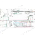
Both full schematic libraries are in here - complete electrical schematics and hydraulic schematics with the fluid power and electrical graphic symbol keys, so you can actually read them. This is what you spread out on the hood when you are chasing a short or figuring out which valve section feeds the auxiliary circuit.
What are the correct charge and pilot pressures? I want to verify my gauge readings.
Straight from the Hydraulic System testing section: charge system pressure is 3300 kPa (480 psi) at high idle, pilot/hydrostatic control pressure is 2500 kPa (365 psi), accumulator charge is 900 kPa (130 psi), and fan drive motor relief is 4430 kPa on the 236/252 or 4550 kPa on the 246/262. The manual gives the tap locations and test conditions so the numbers actually mean something.
Which machines exactly does this cover? Mine is a 246 with a 5SZ serial number.
It covers the 236, 246, 252 and 262 with serial prefixes 4YZ, 5SZ, FDG and CED - the 2004-2011 era machines. Your 5SZ 246 is squarely in it. Check your serial plate before buying; the later B and B3 series machines use different manuals.
![Caterpillar 311 repair manual - Electrical & Starting System, [Elec #12-1] Wiper System Problem](https://youfixthis.com/wp-content/uploads/2019/12/caterpillar-311-repair-manual-9lj00262-up-excavator-page-575-150x150.webp)
Reviews
There are no reviews yet.