


Looking for the factory operating and maintenance guidelines for your 2007 Loadall? This 308-page JCB 531-70 operator manual PDF (OEM #9811/5800) breaks down daily checks, safety procedures, and load charts for the 533-105, 535-95, 535-125 HiViz, 535-140 HiViz, 536-60, 536-70, 540-140, 550-140, 540-170, 550-170, and 541-70 variants. You get complete routine service schedules, detailed dashboard indicator explanations, and a full section on proper operating practices. Open to the maintenance chapters to find exact fluid capacities, greasing point locations, and boom wear pad clearances. Torque the wheel nuts to 680 Nm and hold the information button for three seconds to reset your service interval indicator after an oil change. Ignoring daily maintenance causes expensive downtime. Grab this bookmarked file, open it on your tablet right in the cab, and keep your machine earning.
What's Inside This JCB 531–550 Loadall Series Operator Manual
| System | Pages | Key Topics |
|---|---|---|
| Safety & Introduction | 9-36 | Safety Notices, Safety Warnings, Safety Check List, Operating Safety, Maintenance Safety, Safety Labels, Machine Description, Identifying Your Machine |
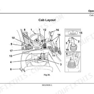
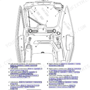
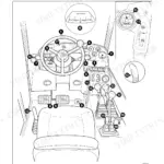
| Cab, Controls & Instruments | 37-82 | Cab Entry and Exit, Seat Controls, Instrument Panel, Air Conditioning and Cab Heater Controls, Boom and Carriage Controls, Load Charts, Load Moment Indicator, Chassis Levelling Option |
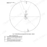
| Safety Equipment & Load Control Systems | 83-107 | Control Locks, LC1 and LC4 Load Control Systems, LC2, LC3 and LC5 Load Control System, Inclinometer, Beacon |
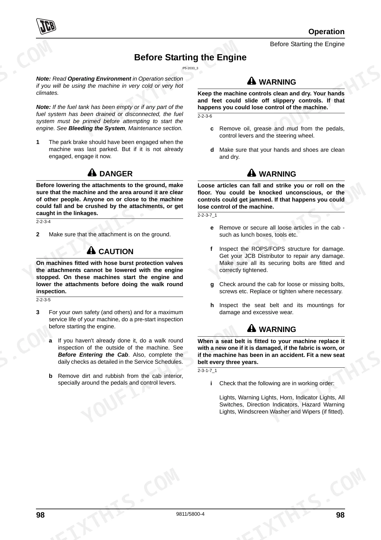
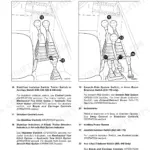
| Starting & Preparing for Travel | 108-117 | Park Brake, Battery Isolator Key, Forward/Reverse Lever, Preparing for Road Travel, Preparing for Site Travel |
| Machine Operation & Site Safety | 118-136 | Limited Slip Differential, Stopping and Parking, Interlock System, Danger Zone, Working with the Boom, Gradients and Slopes, Operating in Low and High Temperatures |
| Towing, Refuelling & Transport | 137-147 | Tow Hitch, Refuelling the Machine, Moving a Disabled Machine, Drawbar Towing, Transporting on a Trailer, Lifting Points, Unladen Weight |
| Storage of the Machine | 148-150 | Storage Area, Preparing for Storage, During Storage, Removing From Storage |
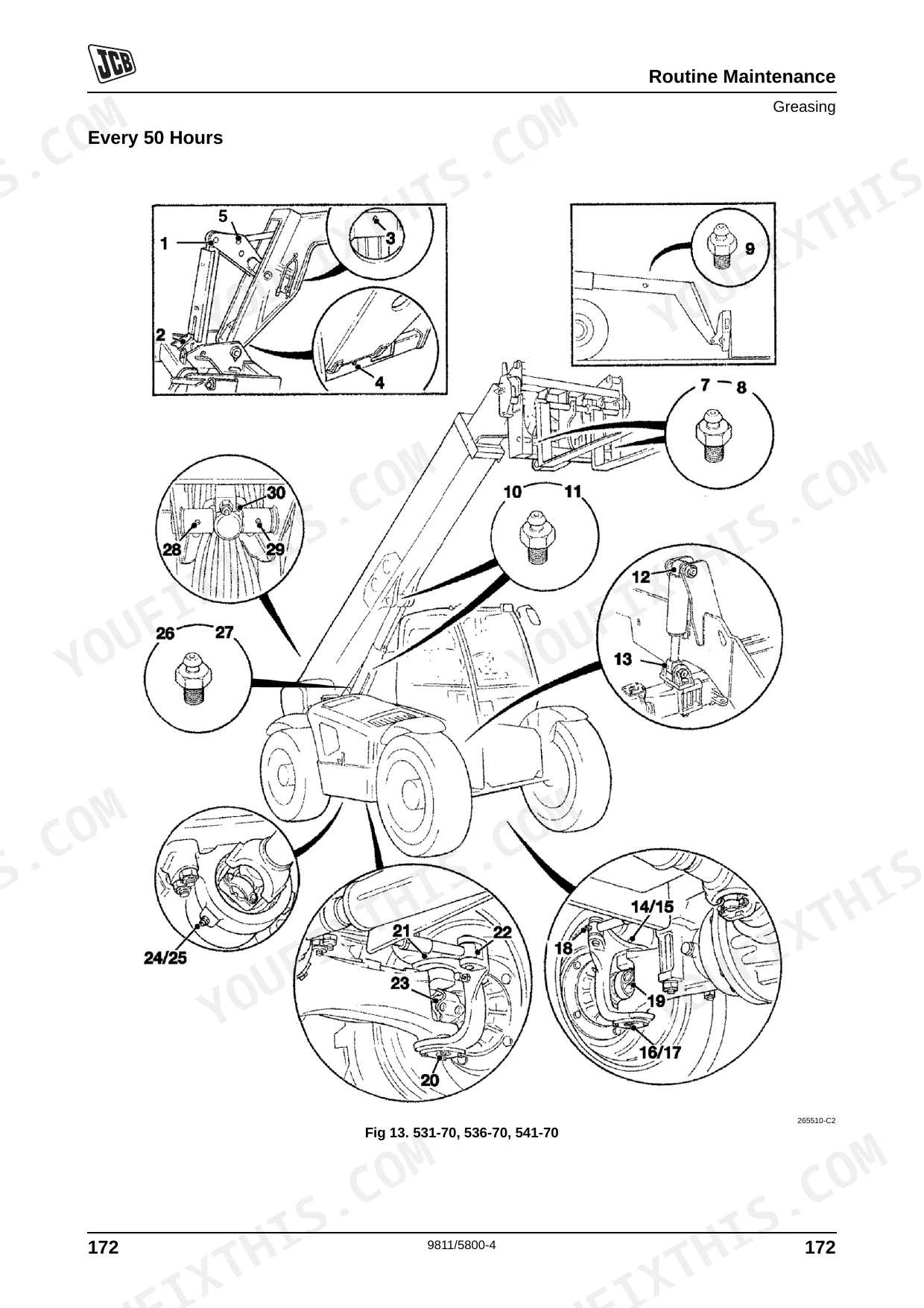
| Routine Maintenance & Service Schedules | 151-194 | Fluids, Lubricants and Capacities, Service Schedules, Pre-Start Cold Checks, Battery Cover, Engine Cover, Rear Cover, Undershield |
| Cab Heater, Boom, Brakes & Electrical | 195-213 | Air Intake Filter, Cab Heater and Air Conditioning, Auxiliary Power Socket, Re-Phasing of 3-Stage Booms, Park Brake Adjustment, Foot Brake, Battery, Fuses, Relays, Jump Starting |
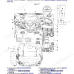
| Engine, Fuel & Hydraulic Systems | 214-235 | Oil and Filter, Cooling System, Front End Accessory Drive Belt, Air Filter, Water Separator and Engine Fuel Filter, Hydraulic Pressure Release, Pilot Filter, Hose Burst Protection Valves |
| Transmission, Tyres & Wear Components | 236-246 | Gearbox, Front and Rear Axle, Powered Track Rods, Tyre Inflation, Wheel Nuts, Manual and Electronic Steer Mode Selector, Boom Wear Pad Clearance |
| Attachments & Accessories | 247-270 | Windscreen Washer, Fire Extinguisher, Optional Attachments, Hydraulic Hose Connections, Quick Release Couplings, Q-Fit Pin Locking, Extension Jib, Fork Mounted Hook, Sideshift Carriage, Roof Truss Jib, Work Platforms |
| Specifications | 271-293 | Static Dimensions, Performance Dimensions, Maximum Wading Depth, Axle Weight Distribution, Machines with Stabilisers, Trailer Towing |
| Noise, Vibration & Warranty | 299-308 | Noise Data, Vibration Data, Machine Service Record Sheet, Installation Checklist, Warranty Service Schedule |
Quick Reference Specifications
| Specification | Value | Page |
|---|---|---|
| Service Interval Reset Procedure | Push and hold Information button for 3 seconds | p. 66 |
| ROPS/FOPS mounting bolts torque | 244 Nm (180 lbf ft) | p. 180 |
| Wheel nut torque | 680 Nm (500 lbf ft) | p. 242 |
| Maximum Wading Depth | 400mm | p. 290 |
| Hydraulic Tow Hitch Max Gross Trailer Weight (HiViz Models) | 3500 kg | p. 293 |
JCB 531–550 Loadall Series Common Problems This Manual Covers
JCB 531-70 steering becomes completely inoperative or wheels stop turning in front-wheel steer mode p. 243
Inspect the steering proximity switch and target disc gap. Check the manual steer mode selector on page 243 for re-phasing procedures. Verify the wheel nuts are tightened to 680 Nm as shown on page 242. Clean any water or debris from the sensor cable.
Manual Section: Wheel AlignmentEngine revs surge erratically and experience sudden speed variation under load or while idling p. 143
Bleed air from the fuel system following the procedure on page 143. Clean the water separator pump and verify the priming pump operates smoothly. Check the fuel filter for blockages. Push and hold the Information button for 3 seconds to reset the service interval on page 66 if replacing filters.
Manual Section: Fuel SystemMachine shuts down or stalls when driving through deep water or muddy site conditions p. 290
Verify the water level does not exceed the maximum wading depth of 400mm listed on page 290. Inspect the electrical connections for water ingress. Check the primary fuses and relays for damage. Drain any accumulated water from the air filter housing.
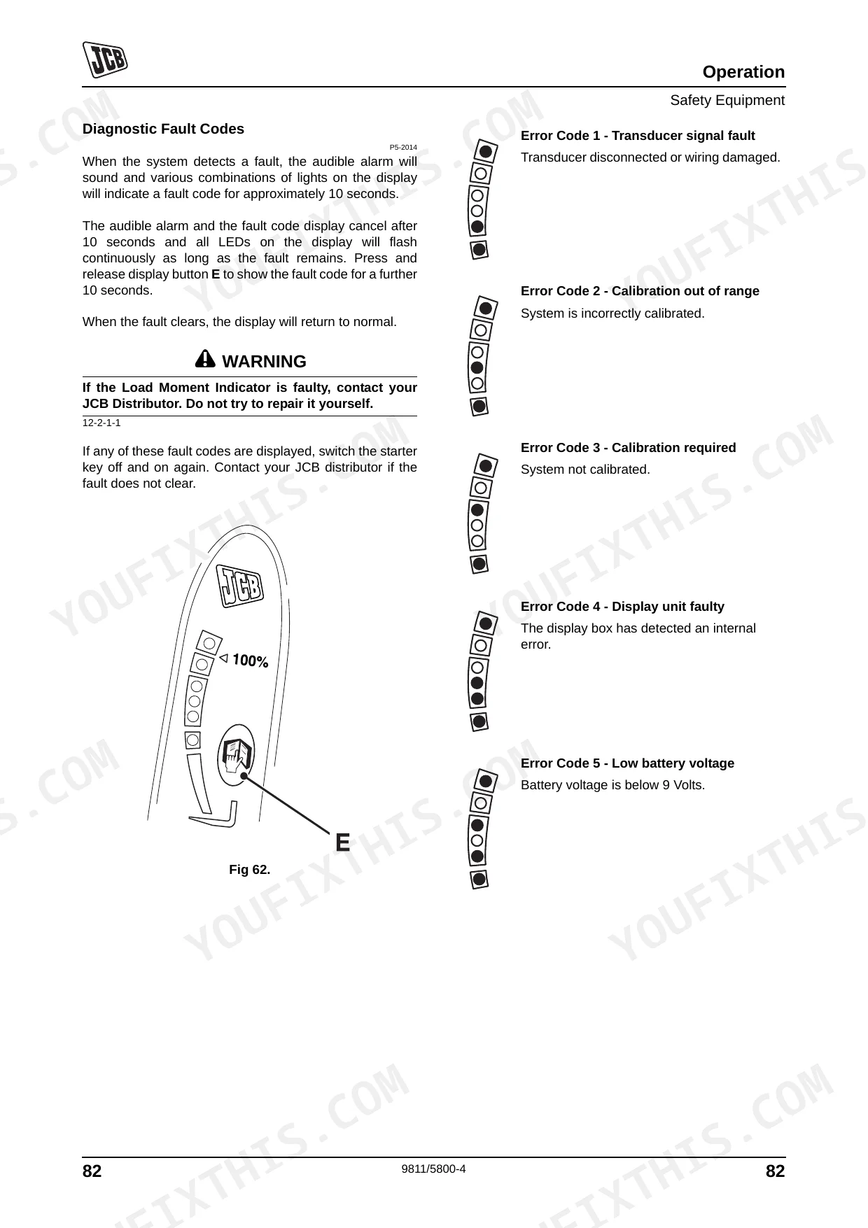
Manual Section: SpecificationsLoad moment indicator displays a transducer signal fault code and flashes continuously on the dashboard p. 92
Review the error code reference on page 92. Check the transducer connections and wiring harness for visible damage. Verify the battery voltage is sufficient. Inspect the ROPS/FOPS mounting bolts and ensure they are torqued to 244 Nm as shown on page 180 before resuming heavy lifting operations.
Manual Section: Safety EquipmentFrequently Asked Questions
How do I reset the JCB telehandler fault code?
Switch the starter key off and on again. If the fault code does not clear after this, contact your JCB distributor for assistance. The manual does not recommend attempting to repair electrical fault codes yourself.
How do I reset the service interval on a JCB 535-125 HiViz?
To reset the service interval indicator, switch on the ignition and navigate to the Time Until Service screen using the Information button. Push and hold the Information button for three seconds until the word RESET flashes once, then release. See page 66 for the complete reset procedure.
What does the JCB LMI / overload warning mean?
The Load Moment Indicator (LMI) warns you when the machine is approaching its maximum working limit and could tip forward. When the load exceeds that limit, the red LED C illuminates and an audible warning activates. Reduce the load or retract the boom to return to a safe working range. See pages 83-107 for full LMI and load control system details.
How do I clear the transmission fault on a JCB Loadall?
If a transmission fault code appears, switch the starter key off and on again. If the fault does not clear, contact your JCB distributor. The manual on page 92 covers fault code display and the key-cycle reset procedure.
How to reset JCB 535-95 telehandler warning light
Press the Information switch to acknowledge the warning, which stops the audible alarm. For any warning that activates while the engine is running, stop the machine as soon as it is safe to do so and identify the underlying fault before continuing operation. See pages 54-70 for the full instrument panel and warning indicator reference.

Reviews
There are no reviews yet.