


Part of the JCB Repair Manuals.
Looking to overhaul your 1996-2005 machine? This 229-page JCB Robot 185, 1105, Robot 1105, JCB skid steer loader, Perkins 1004-4HR, Perkins 1004-42AR service manual PDF (OEM #9803/8510) breaks down every hydrostatic pump and wheel hub assembly. You get full hydraulic schematics for the Series 40 pump, complete electrical circuit diagrams, and a thorough section of troubleshooting charts for the drive system. Open up to exploded views showing precise seal replacement procedures and step-by-step engine removal instructions. Lock down the 1/4-inch UNF Grade S bolts to exactly 14 Nm and confirm the transmission has a steady oil supply before testing forward movement. A dead loader ruins your schedule. Grab this bookmarked file right on your tablet, jump straight to the required schematic, and start wrenching.
What's Inside This JCB ROBOT 185 & variants Manual
| System | Pages | Key Topics |
|---|---|---|
| General Information | 6-17 | Identifying Your Machine, Torque Settings, Service Tools, Sealing and Retaining Compounds |
| Care and Safety | 18-27 | Safety Notices, General Safety, Operating Safety, Maintenance Safety, Safety Decals |
| Routine Maintenance | 28-59 | Fluids, Capacities and Lubricants, Fuel System, Service Schedules, Loader Arm Safety Strut, Greasing, Electrical System, Hydraulic System |
| Optional Attachments | 60-69 | Quick Release Couplings, Connecting/Disconnecting Hoses, Shovels, Pallet Forks, Manure/Silage Fork with Top Grab, Attachment Frame, Problem Solving |
| Body and Framework | 70-81 | Seat and Floor Plate, Glazing, Door, Loader Arm |
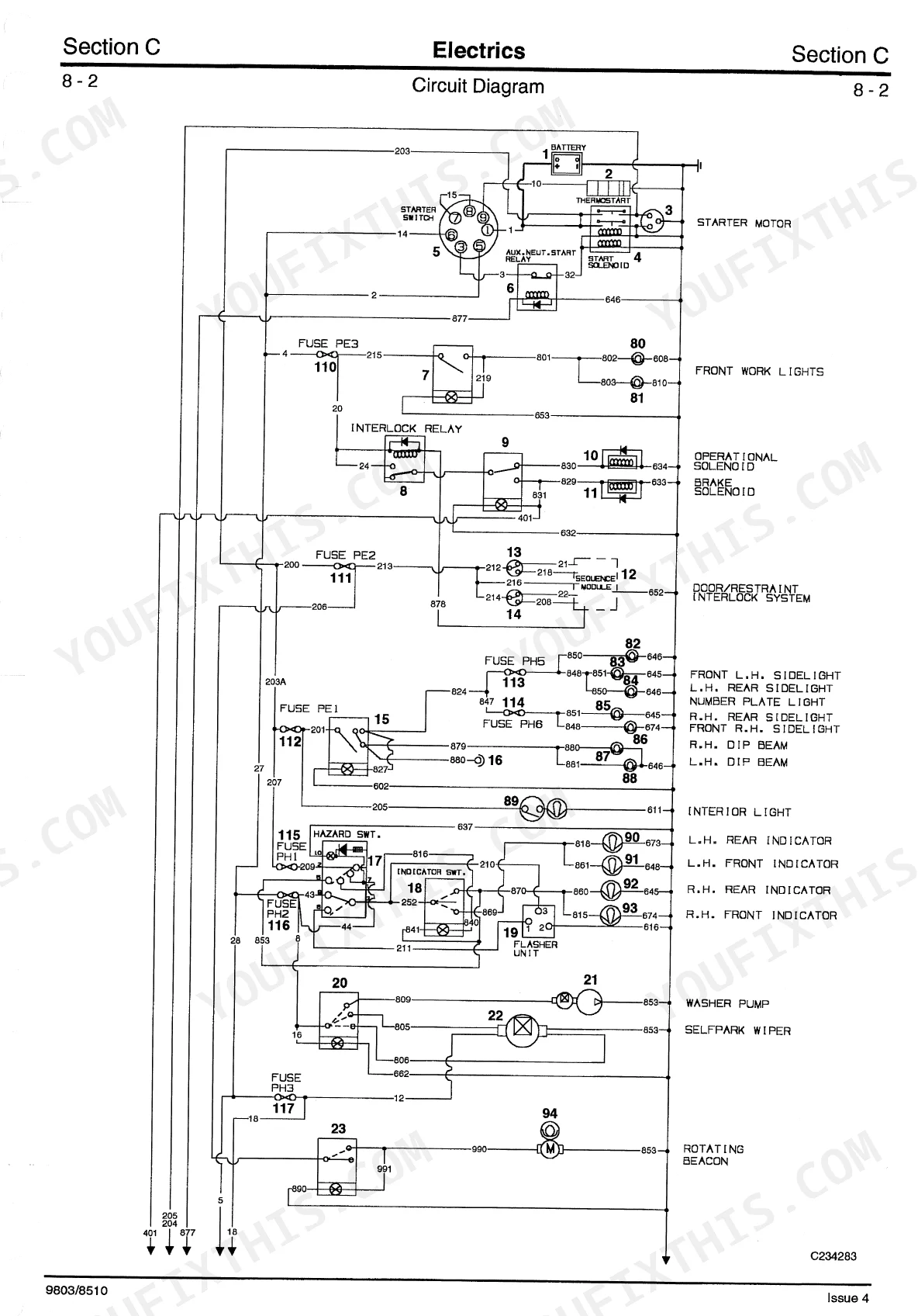
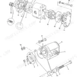
| Electrics | 82-107 | Technical Data, Test Methods, Battery, Alternator, Starter Motor, Circuit Diagrams |
| Controls | 108-111 | Safety Restraint Bar, Locking Mechanism |
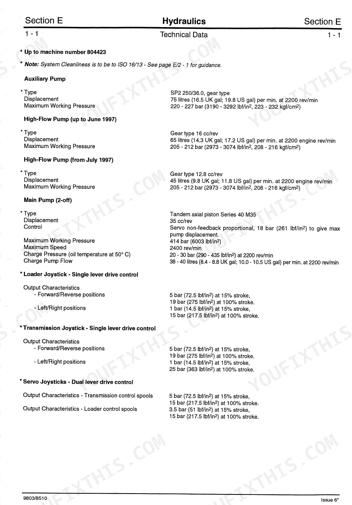
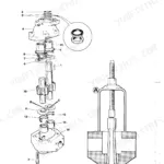
| Technical Data | 114-119 | Auxiliary Pump, High-Flow Pump, Main Pump, Loader Joystick, Transmission Joystick, Servo Joysticks, Hydraulic Motors, Loader Valve Block |
| Descriptions | 120-138 | Hydraulic Contamination |
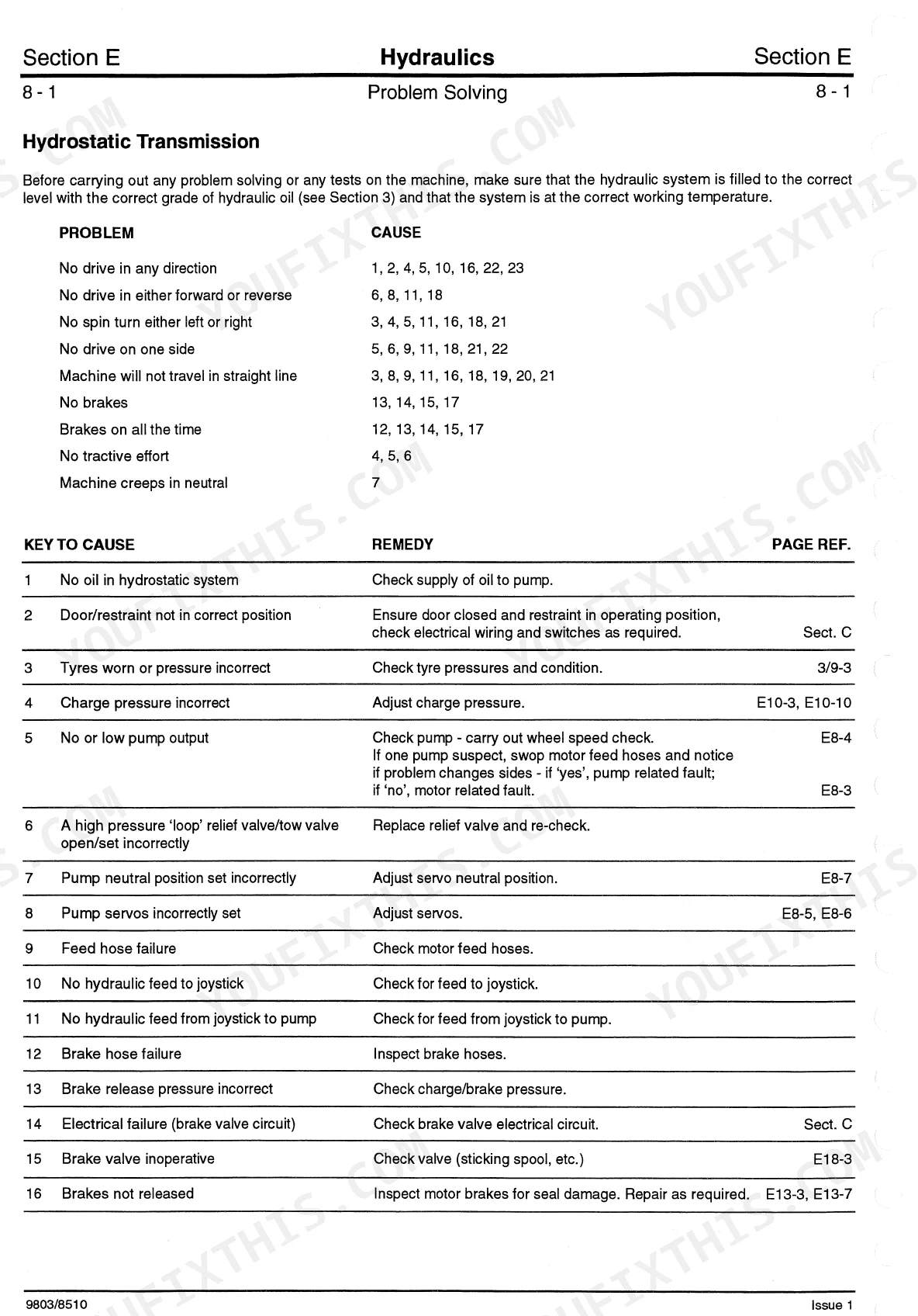
| Problem Solving | 139-145 | Hydrostatic Transmission, Hydraulic System, Pump, Motor, Servo Unit, Brake Valve, Joystick, Chain |
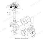
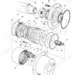
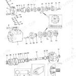
| Pumps | 146-174 | Main Pump, Pump/Engine Couplings, Series 40 Hydrostatic Pump, Auxiliary Pump, High-Flow Pump, Series 42 Hydrostatic Pump, Drive Motor |
| Valves | 175-185 | Loader Valve, Main Relief Valve, Auxiliary Relief Valves, Pressure Reducing Solenoid Valve, Brake Valve |
| Servo Joysticks | 186-188 | Joystick Flange, Hydraulic Flexible Hoses, Electrical Connection, Handle Assembly, Valve Body, Valve Units |
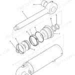
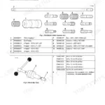
| Rams | 189-194 | Lift and Compensating Rams, Crowd Ram, Piston Head, Rod Seals, Piston Rod |
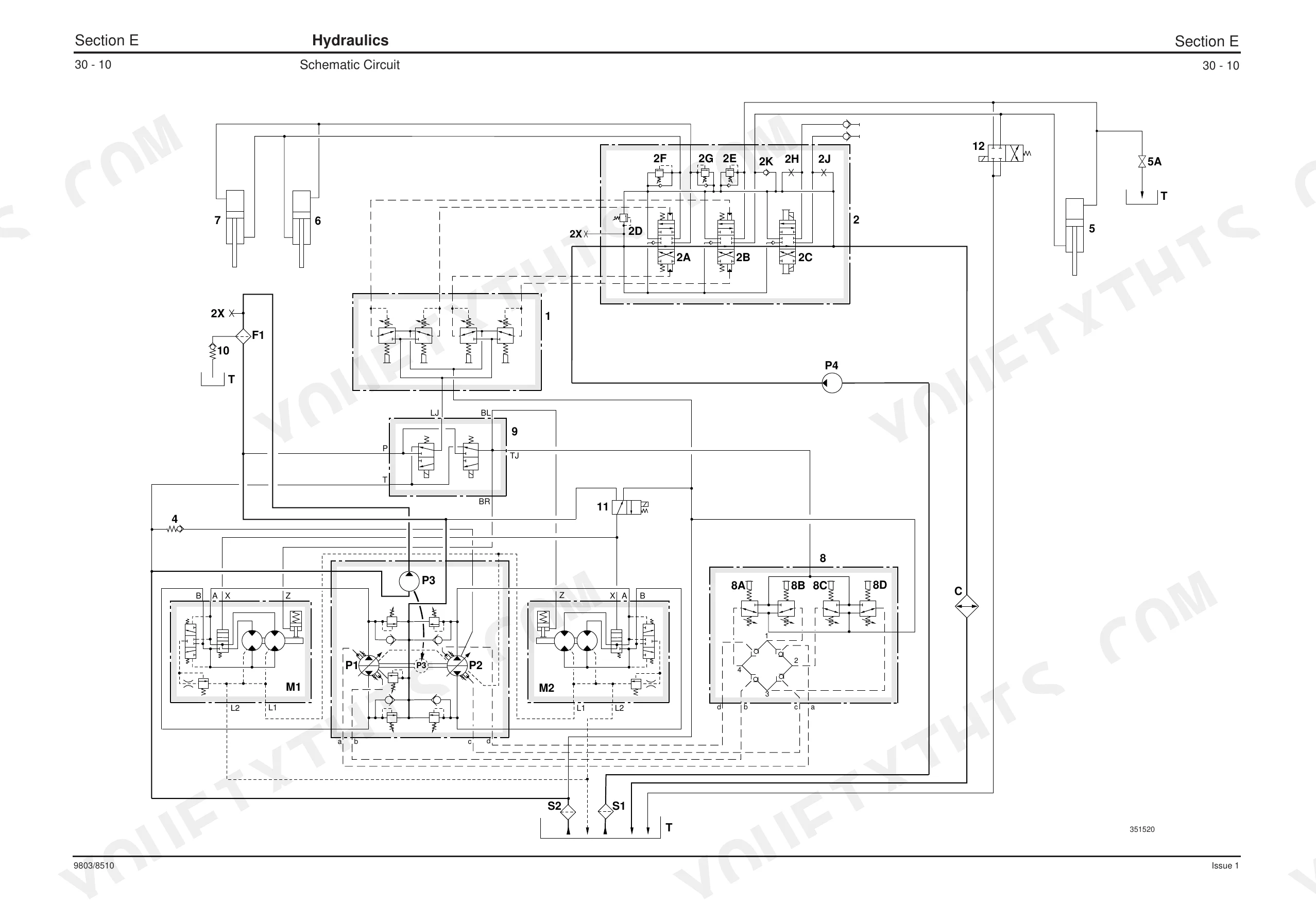
| Schematic Hydraulic Circuit | 195-213 | Hydraulic Tank, Hydraulic Filter |
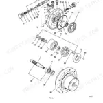
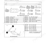
| Transmission | 214-221 | Tyres and Wheels, Wheel Hub Assembly |
| Brakes | 222-225 | Towing/Winching |
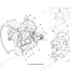
| Engine | 226-229 | Technical Data, Removal and Replacement |
Quick Reference Specifications
| Specification | Value | Page |
|---|---|---|
| All Models | ||
| UNF Grade 'S' Bolts Torque Setting (1/4 inch bolt) | 14 Nm (1.4 kgf m, 10 lbf ft) | p. 9 |
| Metric Grade 8.8 Bolts Torque Setting (M5 bolt) | 7 Nm (0.7 kgf m, 5 lbf ft) | p. 9 |
| Hydrostatic Transmission Problem: No drive in any direction | Check supply of oil to pump. | p. 139 |
| Hydraulic connections torque | 30 Nm (22 lbf ft, 3 kgf m) | p. 186 |
| Loader Valve Tie Rod 10 torque | 44.75 Nm (33.0 lbf ft, 4.6 kgf m) | p. 178 |
| Main Hydraulic Filter Type | High Pressure Spin - On, 5 micron | p. 115 |
| High-Flow Filter Type | 17 micron | p. 115 |
| Series 40 Hydrostatic Pump | ||
| Shaft Seal Replacement | See page 152 for the shaft seal replacement specification | p. 152 |
| Drive Motor up to machine no. 804075 | ||
| O-rings, Sealing Rings, Gaskets Replacement | discarded and replaced by new ones | p. 168 |
| all (up to machine number 804423) | ||
| Main Pump (2-off) Maximum Working Pressure | 414 bar (6003 lbf/in2) | p. 114 |
| Auxiliary Pump (up to machine number 804423) | ||
| Auxiliary Pump Displacement | 75 litres (16.5 UK gal; 19.8 US gal) per min. at 2200 rev/min | p. 114 |
| Loader Joystick (up to machine number 804423) | ||
| Loader Joystick (Single lever drive control) Forward/Reverse positions output at 100% stroke | 19 bar (275 lbf/in2) | p. 114 |
JCB ROBOT 185 & variants Common Problems This Manual Covers
JCB Robot 185 loader arms bleed down and lose holding force when parked or under heavy load p. 131
Inspect the load hold check valve on page 131 to verify it closes fully to stop the load from dropping. Check the boom lift ram piston head and torque the settings to 405 Nm (299 lbf ft / 41.3 kgf m) according to the specifications on page 116.
Manual Section: HydraulicsHydrostatic transmission feels under-powered and machine exhibits weak drive performance or no drive in any direction p. 139
Test the main pump maximum working pressure. Verify it reaches 414 bar (6003 lbf/in2) as specified on page 114. If pressure is low, follow the troubleshooting procedures on page 139 to check the oil supply. Replace the 5 micron high pressure spin-on filter referenced on page 115.
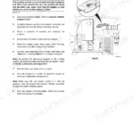
Manual Section: Hydraulic System Problem Solving (Hydrostatic Transmission)Tight engine compartment clearance makes it extremely difficult to access and remove the engine oil filter p. 52
Drain the 10.7 litres (2.4 UK gal / 2.8 US gal) of engine oil before starting. Remove the filter using a chain wrench if necessary, as noted on page 52. Start the engine and verify the hot oil pressure reads at least 2.0 bar (30 lbf/in2) on page 227.
Manual Section: Engine Routine MaintenanceBattery drains quickly and electrical system loses voltage during operation while the engine is running p. 83
Measure the alternator maximum output using a multimeter to confirm it produces 65 Amp as detailed on page 83. Check the alternator belt slack and adjust it to exactly 10 mm (3/8 in) per the instructions on page 57. Tighten any loose M5 grade 8.8 bolts to 7 Nm.
Manual Section: Alternator Charging Test and FaultsFrequently Asked Questions
What are the torque specs for JCB Robot 185/1105 wheel motors, hubs, or hydraulic components?
For wheel bolts, tighten to 405 Nm (298 Ibf ft, 41 kgf m) when refitting the rear wheel. Hydraulic connections for the main pump should be torqued to 45 - 50 Nm (4.6 - 5.1 kgf m, 33 - 37 Ibf ft). When fitting the new pump/engine coupling, coat threads of capscrews E with JCB Threadlocker and Sealer and torque tighten to 28 Nm (21 Ibf ft, 2.8 kgf m).
How do I calibrate or relearn the controls on a JCB Robot 185/1105?
The manual describes various adjustments for specific control issues, rather than a general calibration or relearn procedure. For instance, if the machine creeps in neutral, adjust the transmission pump servo piston by loosening lock nut A and turning the 'neutral' adjusting screw B 1/10 of a turn in the required direction, then re-tighten the lock nut. This adjustment is very sensitive, requiring small turns and re-checking.
What are the replacement specifications for Hydraulic seals?
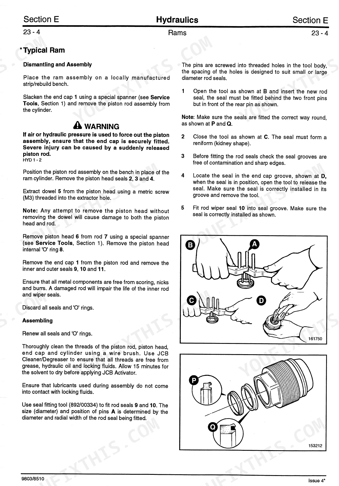
When replacing hydraulic seals, always use new seals and lubricate them with grease or petroleum jelly during reassembly. For the Series 40 Hydrostatic Pump shaft seal, press the new seal into the seal cover ensuring the seal lips face outwards. For typical ram rod seals, use a seal fitting tool (892/00334) and ensure the seal is fitted behind the two front pins, forming a reniform (kidney) shape.
How do you fix JCB Robot 185 loader arms bleed down and lose holding force when parked or under heavy load?
Inspect the load hold check valve on page 131 to verify it closes fully to stop the load from dropping. Check the boom lift ram piston head and torque the settings to 405 Nm (299 lbf ft / 41.3 kgf m) according to the specifications on page 116.
What format is this manual in?
Immediate download of the complete 229-page searchable Service Manual. Access it on any device, from a laptop at your desk to a phone in the field.
Are there any print restrictions on this manual?
The PDF is DRM-free. Print whatever sections you need to take out to the shop. Standard letter or A4 paper works.
Does this Service Manual have electrical diagrams?
Included. The JCB Robot 185 & variants Service Manual covers complete wiring harness diagrams, electrical circuits, and connector pinouts.
Reviews
There are no reviews yet.