

Part of the JCB Repair Manuals.
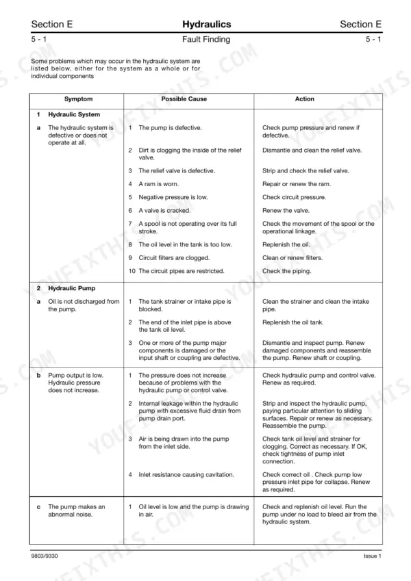
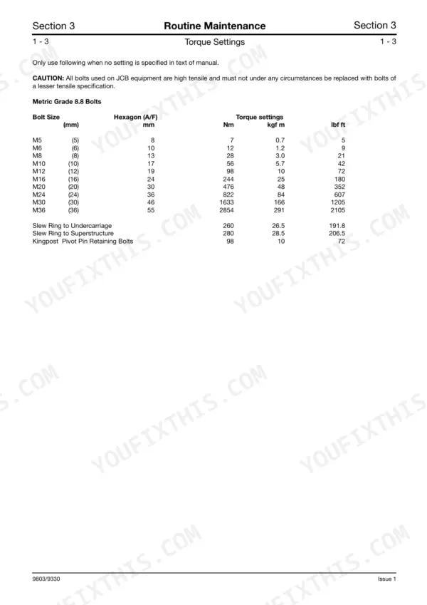
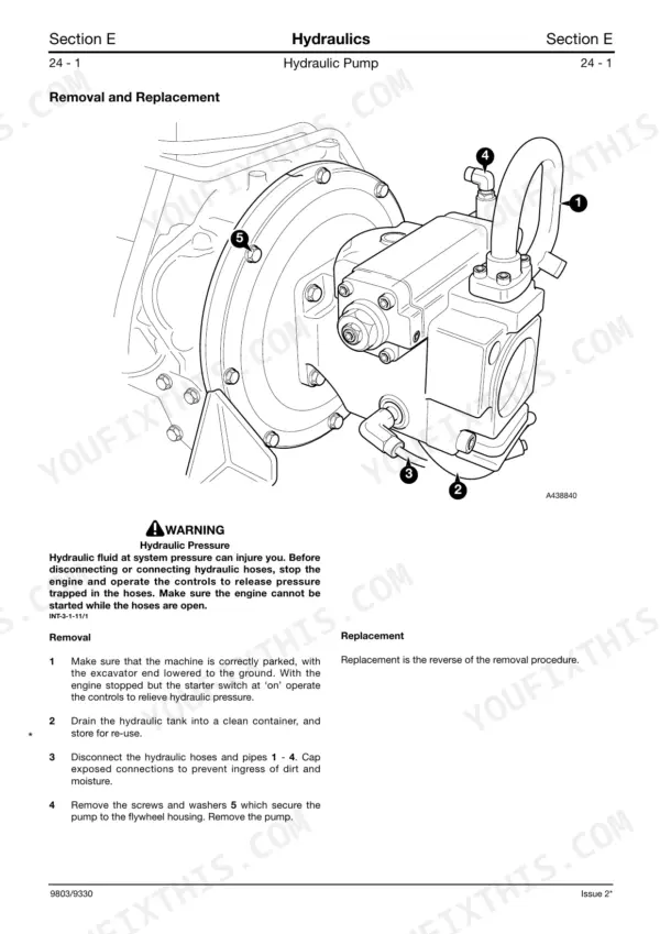
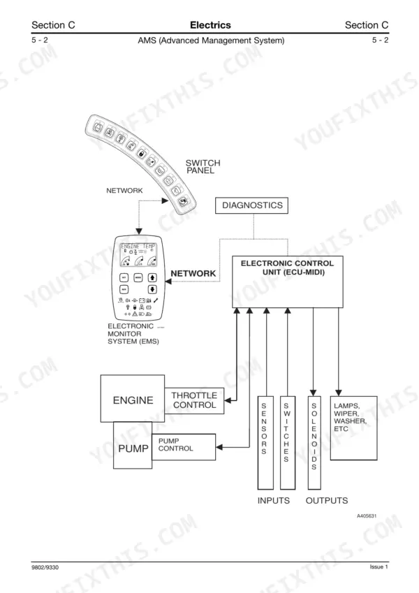
Looking for the factory repair procedures for your midi excavator? This 401-page JCB 8080 Service Manual PDF (OEM #9803/9330 Issue 3) breaks down the complete hydraulic system, track running gear, and upper structure components. You get detailed hydraulic schematics mapping out control valve fluid routing, full electrical wiring diagrams to trace shorts, and step-by-step track and idler wheel replacement procedures. Open up the advanced management system section to find exact error codes and heavy-duty troubleshooting charts. Lock down the slew ring to the undercarriage at exactly 260 Nm, then hit the kingpost pivot pin retaining bolts with 98 Nm of torque before testing the boom. Every minute your excavator sits dead costs you money. Grab this bookmarked file, pull it up on your tablet in the shop, and get to work.
Complete the set for your 8080, 4JG1
- Operator Manual: JCB 8080 Midi Excavator Operator Manual
What's Inside This Manual
| System | Pages | Key Topics |
|---|---|---|
| General Information | 4-56 | Identifying Your Machine, Identification Plates, Operation, Before Entering the Cab, Entering/Leaving the Cab, Opening and Closing the Door |
| Care & Safety | 57-62 | Safety Notices, General Safety, Operating Safety, Maintenance Safety |
| Routine Maintenance | 63-95 | Lubricants and Capacities, Coolant Mixtures, Torque Settings, Hydraulic Fittings and Torque Settings, Service Schedules, Revised Service Schedules - Rockbreaker Usage |
| Body & Framework | 96-131 | Service Tools, Technical Data, Basic Operation, Fault Finding, Service Procedures, Cab, Upper Structure, Bucket Ram Pivot and Linkage |
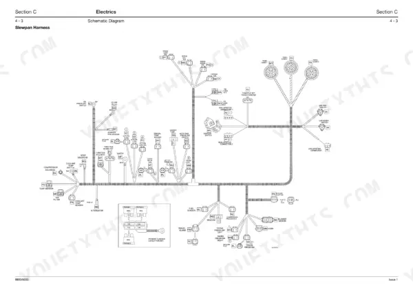
| Electrics | 132-254 | Service Tools, Technical Data, Fuses, Relays, Basic System Operation, Component Identification, Schematic Diagram, Ams (Advanced Management System) |
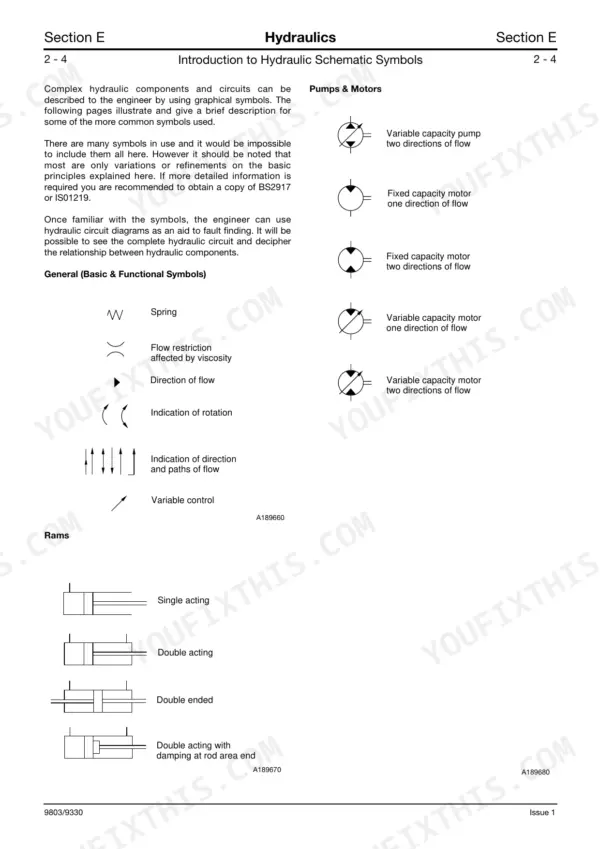
| Hydraulics | 255-358 | Service Tools, Technical Data, Hydraulic Contamination, Introduction to Hydraulic Schematic Symbols, Control Valves, Energy Transmissions and Conditioning, Control Mechanisms |
| Transmission | 359-368 | Technical Data, Traction Motor/Reduction Gear, Removal and Replacement, Motor Bleeding |
| Track and Running Gear | 369-399 | Technical Data, Tracks, Replacement, Replacing a Shoe Plate, Replacing the Track Link, Changing From Steel to Rubber Tracks, Idler Wheel and Recoil Unit |
| Engine | 400-401 | Technical Data |
Quick Reference Specifications
| Specification | Value | Page |
|---|---|---|
| Slew Ring to Undercarriage Torque | 260 Nm (26.5 kgf m) (191.8 lbf ft) | p. 67 |
| Kingpost Pivot Pin Retaining Bolts Torque | 98 Nm (10 kgf m) (72 lbf ft) | p. 67 |
| Oil Seals Replacement | Renew whenever disturbed unless otherwise instructed | p. 62 |
| Slew Motor Oil Seal 7 Replacement | Renew any oil seal if damage to the lip is apparent. New seals must be used when reassembling the motor. | p. 345 |
| Gaskets Replacement | Renew whenever disturbed unless otherwise instructed | p. 62 |
| SAE Tube Size 12 (1.1/16 - 12 Thread Size) Tightening Torque | 190 - 210 Nm (141 - 155 lbf ft) | p. 68 |
| Hose Size 1/2” BSP Tightening Torque | 55 Nm (40 lbf ft) | p. 68 |
| Hydraulic Oil Filler Cap Condition | Tightly closed | p. 8 |
| Track Tension (Hard Ground) | 180 - 205 mm | p. 89 |
| Track Tension (Soft Sand/Sticky Mud) | 250 - 275 mm | p. 89 |
| Hydraulic Pump Maximum Flow | 170 l/min (37.4 gal/min) @ 2300 rev/min | p. 258 |
| Hydraulic Pump Flow at 12.0 MPa | 163 l/min | p. 295 |