


![John Deere 200CLC 230CLC 270CLC Repair Manual [Excavator]](https://youfixthis.com/wp-content/uploads/2012/02/Manual_Download-300x300.jpg)
Part of the John Deere Repair Manuals.
This is the complete John Deere factory repair manual (TM4559) for the 6110, 6210, 6310, 6410 and 6510 tractors, including all L (Limited) and S (Standard) cab variants built from 1996 to 2001. Across 1,566 pages it covers every system on the machine: the 4045TL four-cylinder turbocharged diesel from slow-idle calibration through full engine removal, the three transmission families (SynchroPlus, PowrQuad, AutoQuad) with their clutch modules and range drives, the complete hydraulic system from the charge pump through every selective control valve, and the full electrical system with wiring harnesses and the electronic monitoring suite. It is the same technical manual a John Deere dealer technician works from, with the torque values, test pressures and clearances called out so the job is done to factory specification the first time.
What's Inside This John Deere 6110-6510 Repair Manual
| System | Pages | Key Topics |
|---|---|---|
| Safety | - | |
| General Information | Specifications, Tune-Up, Predelivery Inspection | |
| Engine | Engine Removal and Installation | |
| Fuel, Air Intake, Cooling and Exhaust Systems | Speed Control Linkage, Fuel System, Air Intake System, Cooling System, Cold Weather Starting Aids, Exhaust System | |
| Electrical System | Connectors, Wiring Harnesses, Charging Circuit, Starting Circuit, Fuses/Relays/Switches, Monitoring System, Electrical Components | |
| SynchroPlus Transmission | Transmission Removal and Installation, Shift Controls, Perma-Clutch 2, Gear Transmission | |
| Power Reverser | Component Removal and Installation, Shift Controls, Power Reverser Module, Gear Transmission | |
| PowrQuad and AutoQuad Transmissions | Transmission Components, Shift Controls, PowrQuad Module, Creeper Transmission, Option Transmission, Range Transmission | |
| Power Train | U-Jointed Shafts and Torsion Damper, FWD Clutch, Differential, Hydraulic Pump Drive, Final Drives, Rear PTO, Front PTO, Front Implement Drive | |
| Steering and Brakes | Hydrostatic Steering, Steering Cylinders, Brake Valve, Rear Brakes | |
| Hydraulic System | Controls, Hydraulic Pump and Charge Pump, Valves, Rockshaft and Rockshaft Cylinder, Three-Point Hitch, Selective Control Valves and Couplers, Independent Control Valve | |
| Miscellaneous | Main Frame, Front Axle, Front and Rear Wheels, Center Link Bracket, Triple Link Suspension (TLS) of FWD Axle | |
| Operator's Cab and 2-Post ROPS | Cab Tilt, Removal and Installation, Controls, Air Conditioning System, Heating System, Seats, 2-Post ROPS, Low Clearance Cab, Electronic Control Components | |
| Special Tools | Dealer-Fabricated Special Tools |
Quick Reference Specifications
| Specification | Value | Page |
|---|---|---|
| All 6110-6510 models | ||
| Engine | John Deere 4045TL series (4-cylinder turbocharged) | |
| 6110, 6110L | ||
| Max. PTO power | 48 kW (65 hp) | |
| 6210, 6210L | ||
| Max. PTO power | 54 kW (72 hp) | |
| 6310, 6310L, 6310S | ||
| Max. PTO power | 60 kW (80 hp) | |
| 6410, 6410L, 6410S | ||
| Max. PTO power | 67 kW (90 hp) | |
| 6510L, 6510S | ||
| Max. PTO power | 71 kW (95 hp) | |
| All models | ||
| Rated engine speed | 2300 rpm | |
| Engine mounting cap screw torque | 100 N.m (75 lb-ft) | |
| Coolant capacity | Approx. 11 L (2.9 US gal.) | |
| Cooling system test pressure | 50-60 kPa (0.5-0.6 bar; 7-8.7 psi) | |
| Radiator cap pressure valve opens at | 70-90 kPa (0.70-0.90 bar; 10-13 psi) | |
| All FWD models | ||
| FWD jointed shaft to drive flange torque | 135 N.m (100 lb-ft) | |
| 6110, 6210, 6310, 6410, 6510 | ||
| Production years | 1996-2001 | |
John Deere 6110-6510 Common Problems This Manual Covers
All hydraulic remotes dead after SCV spacer or SCV stack service
Disassemble the SCV stack following the Hydraulic System section and confirm the dime disc (part R95493) is seated in the correct slot between the SCV block and the power beyond block, not in the power beyond block slot. Also verify the longer SCV studs are fully threaded and torqued without damaged threads, and check the power beyond block o-ring for proper seating before reassembly.
Manual Section: Hydraulic SystemEngine overheats during field operation, especially in summer or under heavy draft load
Service the cooling system per the Fuel, Air Intake, Cooling and Exhaust Systems section: flush the radiator, pressure-test the system to 50-60 kPa (7-8.7 psi) to locate any internal leak, confirm the radiator cap opens within 70-90 kPa (10-13 psi), and replace the thermostat if opening temperature is out of spec. Coolant capacity is approx. 11 L (2.9 US gal.) - check for low level before condemning the water pump.
Manual Section: Fuel, Air Intake, Cooling and Exhaust SystemsHarsh or jerky gear changes on a PowrQuad or AutoQuad-equipped 6310/6410/6510.
Check the PowrQuad module for correct transmission oil level and inspect the shift control solenoids and hydraulic passages as described in the PowrQuad and AutoQuad Transmissions section. Harsh shifts are often caused by worn clutch pack friction discs in the PowrQuad module or a sticking solenoid reducing modulation pressure, both of which are covered in the module disassembly and rebuild procedure.
Manual Section: PowrQuad and AutoQuad TransmissionsWarning lights illuminate intermittently or monitoring system gives false alarms
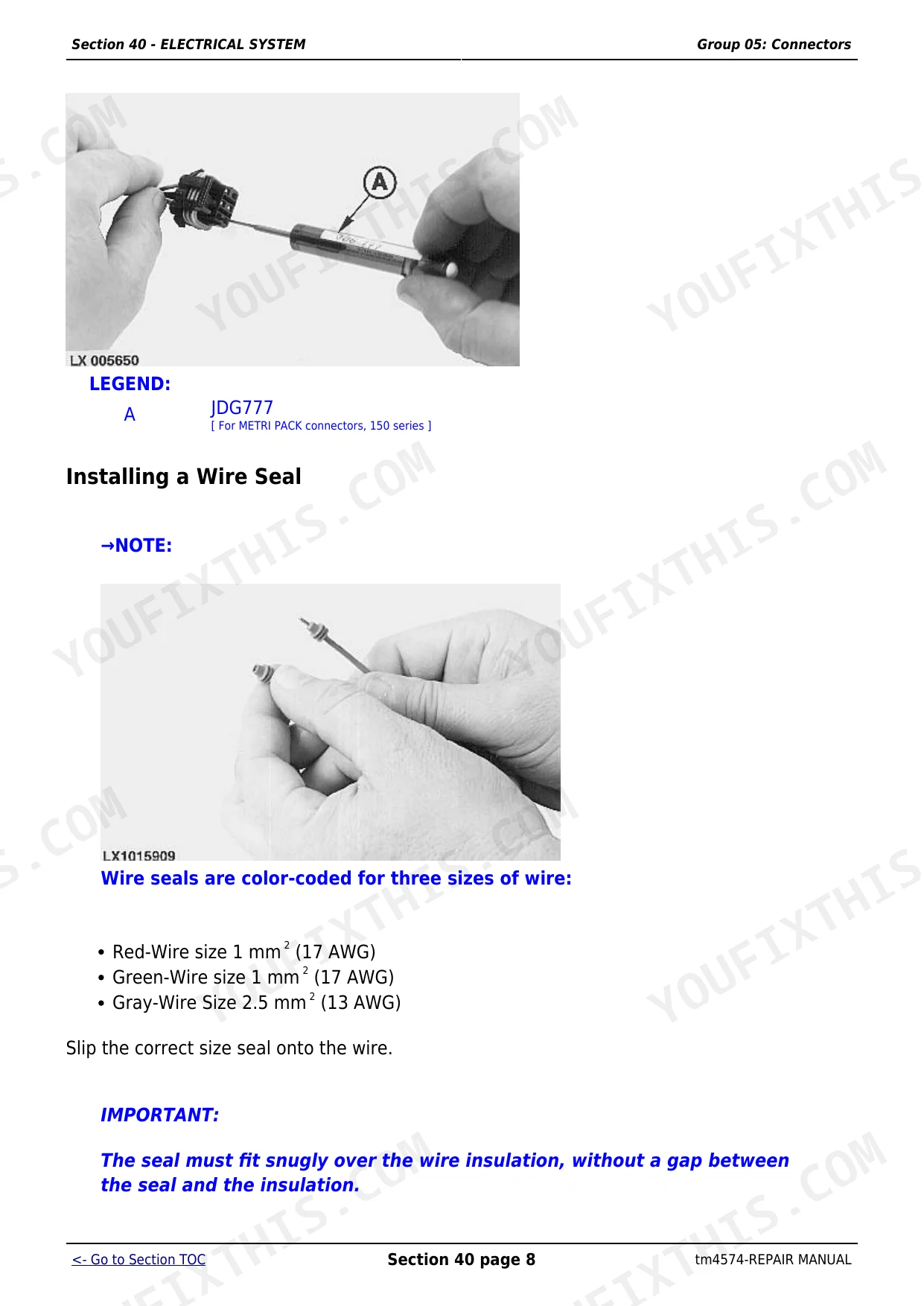
Start with the connector inspection procedure in the Electrical System section before replacing any sensor or instrument. The 6000 Series is known for corroded or spread pin connectors in the main cab harness, particularly above the engine and near the air conditioning compressor. The section covers connector repair tools and pin replacement techniques to restore a reliable circuit without replacing the full harness.
Manual Section: Electrical SystemFrequently Asked Questions
What engine is in the John Deere 6110, 6210, 6310, 6410 and 6510 tractors?
All models in this series run the John Deere 4045TL four-cylinder turbocharged diesel. PTO power ranges from 48 kW (65 hp) on the 6110 up to 71 kW (95 hp) on the 6510S. The General Information section lists the full specifications table by model so you can confirm the exact output and service data for your machine before any engine work.
Why do the hydraulic remotes stop working completely after SCV service on a 6310 or 6410?
The most common cause is a missing or misplaced dime disc (John Deere part R95493) that sits between the SCV block and the power beyond block. Without it the load-sense circuit bleeds internally and no remote will activate. The Hydraulic System section covers disassembly and reassembly of the SCV stack in sequence so you can confirm the disc is seated in the correct slot before closing up.
What transmission options are covered in this repair manual?
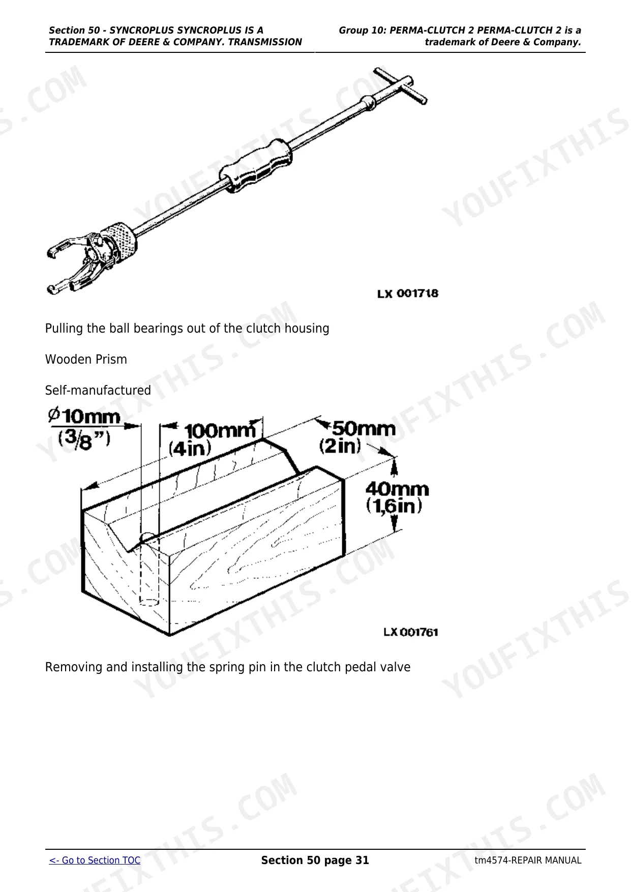
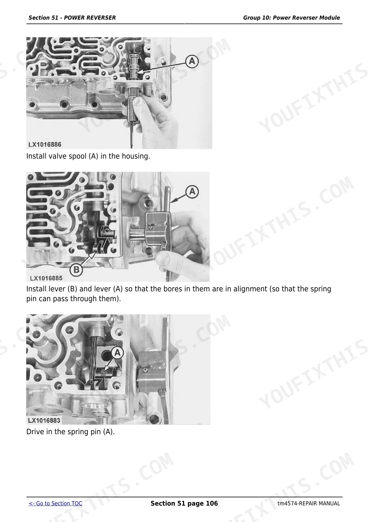
The manual covers three transmissions fitted to these tractors: the SynchroPlus (Section 50), the Power Reverser (Section 51) and the PowrQuad/PowrQuad Plus/AutoQuad (Section 55). Each section covers module removal, shift control adjustment, clutch pack service and range transmission rebuild, so the manual is useful regardless of which gearbox your tractor has.
Does this manual include wiring diagrams and electrical troubleshooting?
Yes. The Electrical System section covers the complete wiring harness layout, connector repair, charging and starting circuits, fuse and relay identification, the monitoring system gauges and warning indicators, and all individual electrical components. That covers the intermittent connector failures and monitoring system faults that are common on higher-hour 6000 Series machines.
Where do I find the torque specs for engine and drivetrain fasteners on the 6110-6510?
The General Information section (Section 10) is the primary torque reference, covering engine mounting at 100 N.m (75 lb-ft), engine support bracket cap screws at 95 N.m (70 lb-ft) and FWD jointed shaft flange cap screws at 135 N.m (100 lb-ft). Additional fastener torques specific to each assembly appear in the relevant repair section throughout the manual.
What do I get after purchasing this John Deere 6110, 6210, 6310, 6410, 6510?
This is a 1566-page searchable PDF (31 MB) ready for immediate download. Works on any device, so pull it up on your phone while you're under the hood. No shipping, no waiting.
Are there any print restrictions on this John Deere 6110, 6210, 6310, 6410?
Yes, print as many copies as you want, and there are no restrictions. Many mechanics print the section they need and bring it to the shop floor.


