


Part of the Yanmar Repair Manuals.
Diagnosing stubborn electrical faults requires factory data, which is exactly what this 222-page Yanmar 3tnv88-u troubleshooting manual pdf (OEM #0DTNV-G00600) lays out for the TNV industrial engine series, including the 3TNV82A, 4TNV88, and 4TNV106 variants. You get complete wiring diagrams and extensive diagnostic trouble code (DTC) lists detailing everything from analog input failures to rack actuator faults. Jump into the factor analysis section to trace EGR step motor shorts, CAN communication errors, and ECU internal temperature faults step-by-step. Verify the accelerator sensor resistance reads exactly 5 ± 1.5kΩ across terminals A-C before replacing parts, and confirm the rack position sensor signal holds steady at 5.0V. Stop throwing expensive sensors at a dashboard warning light. Download this bookmarked PDF right to your laptop, find the exact error code, and get the engine running again.
What's Inside This Yanmar 3TNV / 4TNV Series Manual
| System | Pages | Key Topics |
|---|---|---|
| Failure Diagnosis | 3-4 | Overview of Failure Categories: Analog Input, Pulse Sensor, Contact output/input, Actuators |
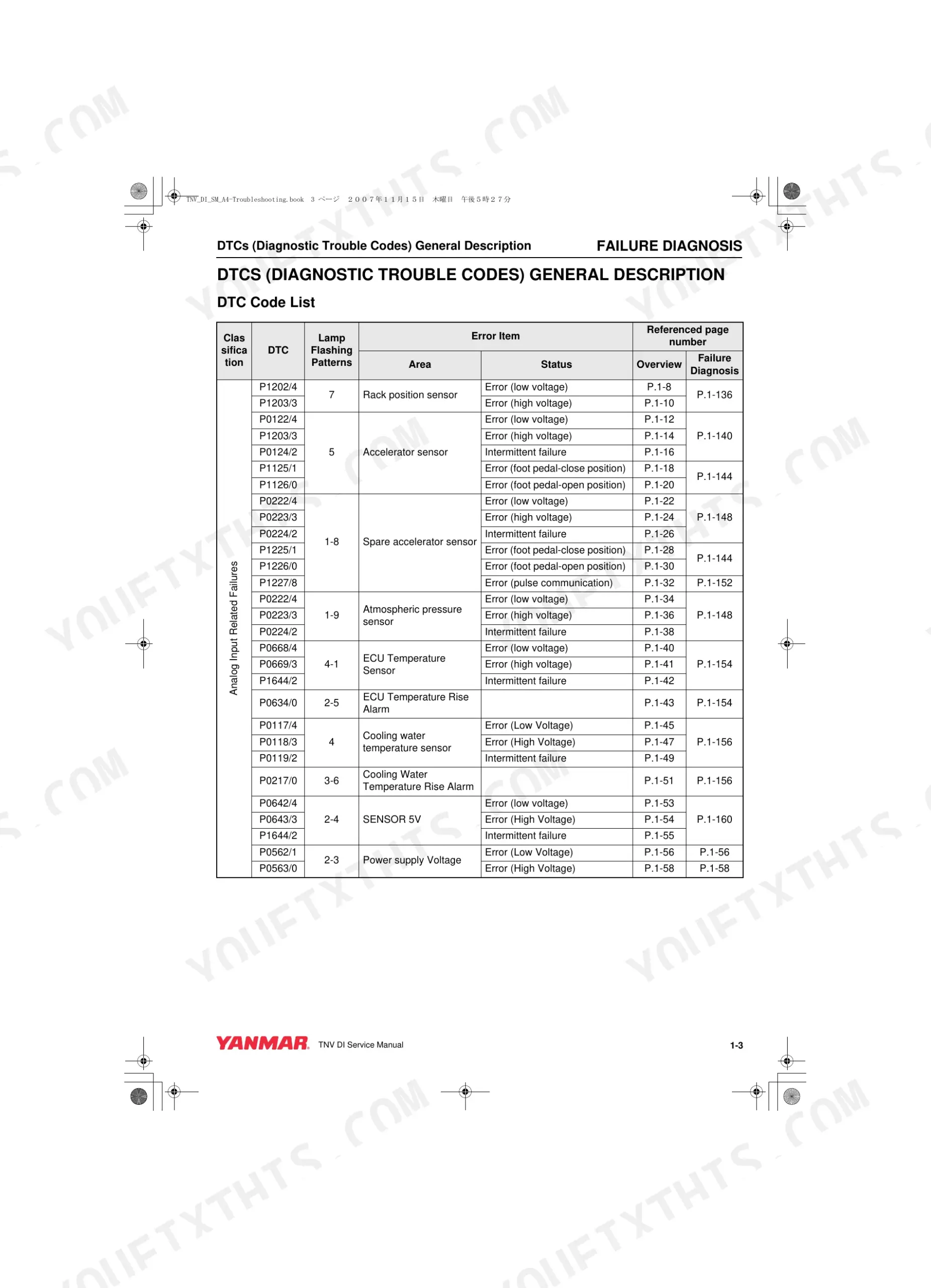
| Dtc Code List | 5-8 | Master Index of Every Fault Code by Number, Fault Name, And Affected Circuit |
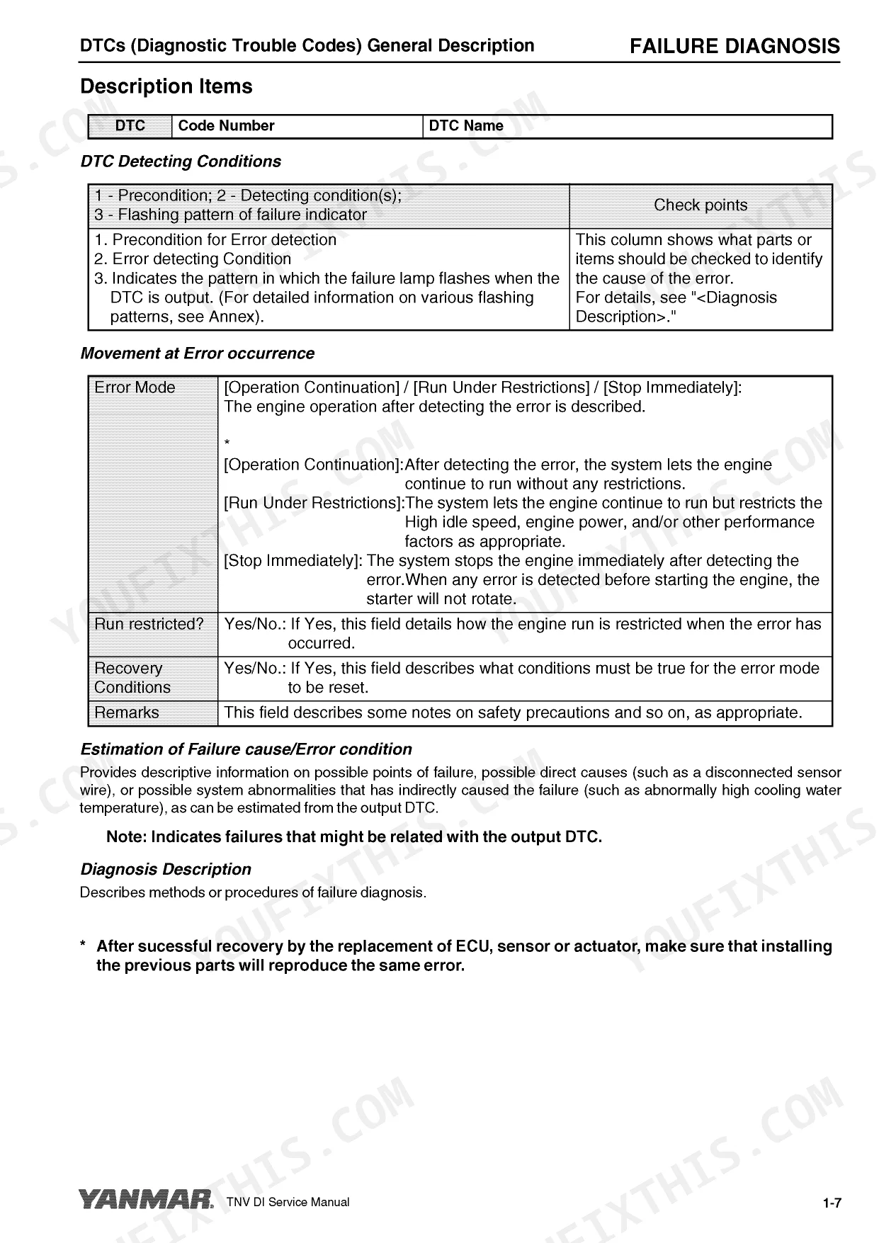
| Description Items | 9 | How Each Entry Is Laid Out: Detection Conditions, Recovery Conditions, And Corrective Action |
| Analog Input Related Failures | 10-61 | Sensor Signal high/low and Open-Circuit Codes (Accelerator, Rack Position, Temperature Sensors) |
| Pulse Sensor Related Failures | 62-67 | Crankshaft and Camshaft Speed-Pickup Signal Loss, Abnormal Pulse Count, And Open or Short Pickup-Circuit Codes |
| Contact Output Related Failures | 68-101 | Relay and Solenoid Output-Circuit Fault Codes |
| Contact Input Related Failures | 102-115 | Switch and Contact Input Fault Codes |
| Actuators Etc. | 116-134 | Rack Actuator, EGR Valve, And Step-Motor Fault Codes |
| Method and Procedure of Failure Diagnosis | 135-209 | Step-By-Step Diagnostic Procedures for Analog Input, Pulse Sensor, Contact output/input, And Actuator Faults |
| Using the Failure Indicator for Failure Diagnosis | 210-211 | Diagnostic Lamp Blink-Count Patterns, Short and Long Flash Sequences, And the Fault Each Blink Code Maps to |
| Factor Analysis | 212-221 | 2G-type Eco-Governor Speed-Fluctuation Causes: Stalling, Surging, And Start-Up Inability |
Quick Reference Specifications
| Specification | Value | Page |
|---|---|---|
| Accelerator sensor resistance value | 5 ± 1.5kΩ | p. 142 |
| Rack Position Sensor Signal Voltage (Low) | 0V | p. 136 |
| Rack Position Sensor Signal Voltage (High) | 5.0V | p. 136 |
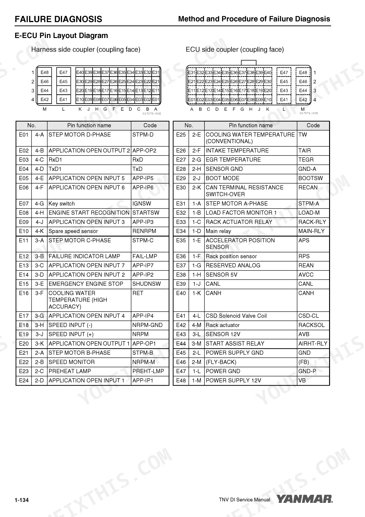
| Accelerator Sensor Resistance (A-C) | 5 ± 1.5kΩ | p. 140 |
| Sensor 5V Normal Voltage | 5V | p. 160 |
| Start Assist Relay Coil Resistance (40A) | 103Ω ± 10% (at 20°C) | p. 174 |
| EGR Valve Coil Resistance | 15 ± 2Ω | p. 185 |
Yanmar 3TNV / 4TNV Series Common Problems This Manual Covers
Intermittent cranking or battery-related no-start condition when trying to turn over the engine.
Check the start assist relay coil resistance. Remove the 40A relay and measure across terminals C and D. Verify the reading matches the 103Ω ± 10% (at 20°C) specification found on page 174. Clean the battery terminals and test the voltage drop across the starting circuit.
Manual Section: Method and Procedure of Failure Diagnosis p. 174Surging RPM, poor throttle response, and loss of power under changing load conditions.
Inspect the EGR valve step motor phases A through D. Measure the coil resistance across the specified terminals using a multimeter. Ensure all phase readings equal 15 ± 2Ω as detailed on page 185. Clean any carbon buildup from the valve body and verify smooth mechanical operation.
Manual Section: Method and Procedure of Failure Diagnosis p. 185Electronic control fault with severe power loss and inconsistent throttle response.
Measure the main sensor power supply voltage at the E-ECU harness connector. Verify the reading falls within the 4.5V to 5.5V range, with a normal target of 5V, as noted on page 160. Inspect the wiring for shorts to ground if the voltage drops below this threshold.
Manual Section: Method and Procedure of Failure Diagnosis p. 160Frequently Asked Questions
How to diagnose a non-start Yanmar TNV Series engine?
To diagnose a non-start condition for a Yanmar TNV Series engine, refer to the "2G-Type Eco-Governor Engine Stalling/Start-Up Inability Factor Analysis". This analysis suggests checking the "whole engine" and considering "Nozzle failure etc." as potential causes for engine stalling or inability to start. This provides a high-level starting point for troubleshooting. p. 213
How to reset Yanmar engine error codes
Yanmar engine error codes are often reset automatically under specific "Recovery Conditions" once the fault is no longer detected. For instance, a Rack Position Sensor Error (P1202/4) will automatically reset when a normal voltage (0.2 to 4.6[V]) is input. For ECU internal errors, the procedure involves rewriting the E-ECU software or replacing the E-ECU, rather than a simple reset. p. 10
What are the replacement specifications for Accelerator sensor?
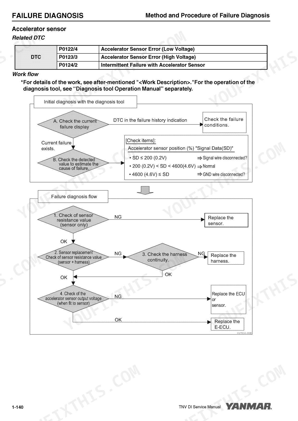
The replacement specifications for the accelerator sensor include a resistance value of 5 ± 1.5kΩ. This value is measured between terminals A and C of the sensor. Checking this resistance is a key step in diagnosing the sensor's functionality and determining if it requires replacement. p. 142
How do you fix Yanmar TNV Series engine experiences a hard start, no-start condition, or unstable idle?
Test the accelerator sensor following the diagnostic test values on page 142. Measure the resistance across terminals A and C. Replace the sensor if the reading falls outside the specified 5 ± 1.5kΩ range. Inspect the wiring harness for damage or loose pins before installing the new unit. p. 142
How quickly can I access this manual after buying?
This is a 222-page searchable PDF ready for immediate download. Works on any device, so pull it up on your phone while you're under the hood. No shipping, no waiting.
Can I print specific sections of this manual?
No restrictions at all. The PDF is DRM-free. Print whatever sections you need to take out to the shop. Standard letter or A4 paper works.
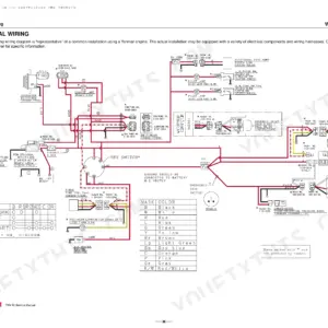
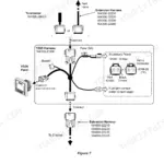
Can I find wiring schematics in this Yanmar TNV Series manual?
Included. The Yanmar TNV Series Troubleshooting Manual provides a wiring diagram for the electrical system.

Reviews
There are no reviews yet.