


Part of the Yanmar Operator Manuals.
Need the factory reference for three machines in one download? This 126-page Yanmar SV05 (EP), SV08-1 (EP), and ViO10-2A (EP) Operator Manual (OEM #LGBAB0-00015) puts every operating procedure for these micro-excavators in one place, from pre-start walkthrough to long-term storage. Inside: a full controls section mapping every lever, pedal, and monitor lamp by model variant, plus lifting capacity charts, hydraulic and wiring diagrams, and a maintenance table covering step-by-step service procedures. You also get a troubleshooting section for engine, electrical, and machine body faults, including a breakdown of phenomena that look like failures but aren't. Replace your main pump outlet hose at 4000 service hours or two years, whichever comes first; torque M8 pipe joint bolts to 12.7-16.7 N·m. Your machine is down and your dealer is three days out. Bookmarked by section and keyword-searchable, pull up the right page in seconds on any device.
What's Inside This Yanmar SV05 (EP), SV08-1 (EP), ViO10-2A (EP) Operator Manual
| System | Pages | Key Topics |
|---|---|---|
| Safety & Precautions | 5-40 | Introduction, Safety Information, Product Overview and Regulation, Operating & Servicing Precautions, Safety Messages and Warning Labels, Precautions When Traveling / Working / Parking, Attachment & Transportation Precautions, Battery Handling, Periodic Replacement of Safety Parts |
| Machine Identification & Ordering Parts | 8-16 | Machine / Engine / EPA Serial Number Plates, Model Designation, Intended Uses, Ordering Replacement Parts and Service Calls |
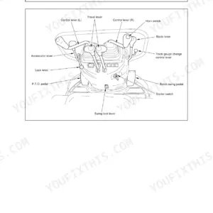
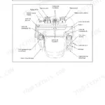
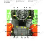
| Controls, Switches & Monitor | 41-46 | Overview of the Machine, Control Levers and Switches, Monitor Alarm Lamps (Oil Pressure, Battery Charge, Water Temp.), Hourmeter |
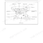
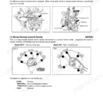
| Operation | 47-66 | Control Levers and Pedals (SV05 / SV08-1 / ViO10-2A), Fuses, Break-In Period, Pre-Start Checks, Operating the Implement, Handling the Rubber Crawler, Hydraulic P.T.O., Machine Transport and Suspension |
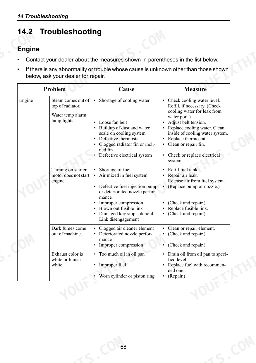
| Troubleshooting | 67-73 | Phenomena That Are Not Breakdowns, Engine, Electrical Equipment, Machine Body |
| Maintenance & Servicing | 74-88 | Filters, Fuel and Oil, Cooling Water, Torque Table, Rubber Crawler Tension, Fan Belt Tension, Greasing, Water Separator and Fuel Filter, Travel Reduction Gearbox Oil, Breaker Service Intervals |
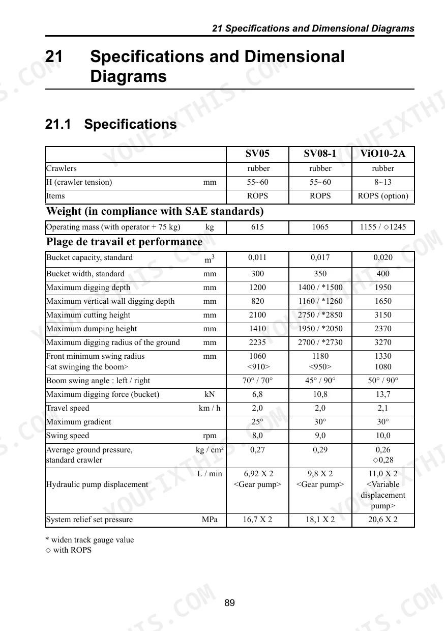
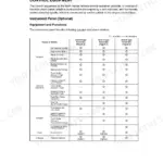
| Specifications | 89-100 | Model View and Working Range, Noise and Vibration Emissions, Lifting Capacity |
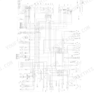
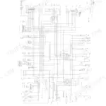
| Hydraulic & Wiring Diagrams | 101-104 | Swing Motor, Travel Motor, Blade / Arm / Boom / Bucket Cylinders, Wiring (Boom Lamp, Horn, Indicator Lamps, Starter Switch, Battery, Fuse) |
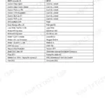
Quick Reference Specifications
| Specification | Value | Page |
|---|---|---|
| All Models | ||
| Main pump outlet hose replacement interval | Earlier of either every 2 years or every 4000 service hours | p. 35 |
| Pipe joint bolt torque (M8) | 12.7 - 16.7 N·m | p. 80 |
| Rubber hose (fuel and cooling water) replacement interval | Every 1000 hours or once a year | p. 83 |
| Fuse capacity (Engine stop solenoid, Fuel feed pump, Timer) | 10 A | p. 58 |
| Fuse capacity (Boom light, Horn, Buzzer, Alarm lamps, Hourmeter, Current limiter, Relay, Cut off valve) | 10 A | p. 58 |
| Hydraulic hose leak detection | Use a piece of cardboard or a plywood block to detect emissions of hot oil. | p. 37 |
| Hydraulic oil level (before start-up, oil temperature 10 to 30°C) | Around the midpoint of the gauge scale | p. 61 |
| Hydraulic oil level (during normal operation, oil temperature 50 to 80°C) | Around the upper limit mark of the gauge scale | p. 61 |
| SV05 | ||
| Rubber crawler tension (H) | 55~60 mm | p. 93 |
| Operating mass (with operator + 75 kg) | 615 kg | p. 93 |
| SV08-1 | ||
| Rubber crawler tension (H) | 55~60 mm | p. 93 |
| Operating mass (with operator + 75 kg) | 1065 kg | p. 93 |
Yanmar SV05 (EP), SV08-1 (EP), ViO10-2A (EP) Common Problems This Manual Covers
Water temperature alarm light illuminates on the dashboard and steam escapes from the radiator
Inspect the cooling system subtank on page 79 and fill to the 0.4 L capacity with Yanmar Genuine Long-Life Coolant. Replace all rubber cooling water hoses if they exceed the 1000 hours or once a year replacement interval as directed on page 83.
Manual Section: Engine Troubleshooting (Cooling System) p. 72Starter switch does not start motor and indicator lamps fail to illuminate on the monitor panel
Remove the fuse box cover located near the operator seat. Inspect the engine stop solenoid and fuel feed pump fuses. Replace any blown fuses with a new 10 A capacity fuse as detailed on page 58. Verify the battery charge alarm lamp goes out after starting.
Manual Section: Fuses p. 53Discontinuous arm movement or shaking bucket paired with hydraulic fluid leaking from main boom hoses
Inspect the main pump outlet hoses for damage. Use a piece of cardboard or a plywood block to detect emissions of hot oil as described on page 37. Replace these hoses if they have reached the 4000 service hours or 2 years limit specified on page 35.
Manual Section: Precautions During Servicing p. 32Frequently Asked Questions
What are the torque specs for the engine bolts on a Yanmar SV05?
The manual provides a "Torque table" for standard tightening torques. For fine thread screws, which are specified for engine use, the tightening torque for M14x1.5 is 127.5 - 147.1 N•m, and for M16x1.5 it is 210.9 - 240.3 N•m. Always be careful when tightening parts made of resin to avoid damage. p. 80
What are the replacement specifications for Hydraulic hoses and seals?
The "Main pump outlet hose (P1, P2, P3)" should be replaced periodically, with intervals of either every 2 years or every 4000 service hours, whichever occurs earlier. When replacing hydraulic hoses, it is essential to replace the O-rings and seals at the same time. For further information about replacing safety parts, contact your dealer. p. 35
What are the replacement specifications for Coolant hoses and clamps?
Rubber hoses for fuel and cooling water should be replaced periodically, either every 1000 hours or once a year, whichever comes earlier. If a hose clamp is found to be deformed or cracked, it must be replaced immediately. For further information about replacing safety parts, contact your dealer. p. 83
How do you fix Yanmar SV05 rubber crawler slipping or tracking improperly to the left or right side?
Check the crawler tension using a grease gun as shown on page 80. Measure the clearance at the track roller. Adjust the track roller so the clearance is exactly 55~60 mm. If tension drops repeatedly during operation, verify the grease nipple valve is tightened properly to prevent pressure loss. p. 80
How will I receive this Yanmar SV05 (EP), SV08-1 (EP), ViO10-2A (EP)?
Immediate download of the complete 126-page searchable Operator Manual. Access it on any device, from a laptop at your desk to a phone in the field.
Can I print this manual?
Yes. The PDF has no DRM restrictions, so print any page or section you need for your shop. Works with any standard printer.
Reviews
There are no reviews yet.