


Part of the Yanmar Repair Manuals.
Diagnosing the engine management on your 5-8 ton mini-excavator requires the hard numbers inside this 162-page Yanmar 3TNV88-Z Electronic Control Manual PDF, which also covers TNV Series variants like the 3TNV84T-Z, 4TNV98T-Z, and 4TNV88-E. Inside, you get complete wiring diagrams mapping out the engine control unit, accelerator sensor, and EGR valve. You also receive a full breakdown of diagnostic trouble codes, freeze frame data logging instructions, and step-by-step software procedures for using the factory service tool. Verify your accelerator sensor is receiving a rated 5 Vdc±0.01V and check that total resistance sits right at 5 ± 1.5kΩ before condemning the harness. Stop throwing expensive sensors at an electrical gremlin. Download this bookmarked file directly to your tablet, find the exact diagnostic test you need, and get that excavator running right.
What's Inside This Yanmar Yanmar TNV Series (R55/R80-7A) Manual
| System | Pages | Key Topics |
|---|---|---|
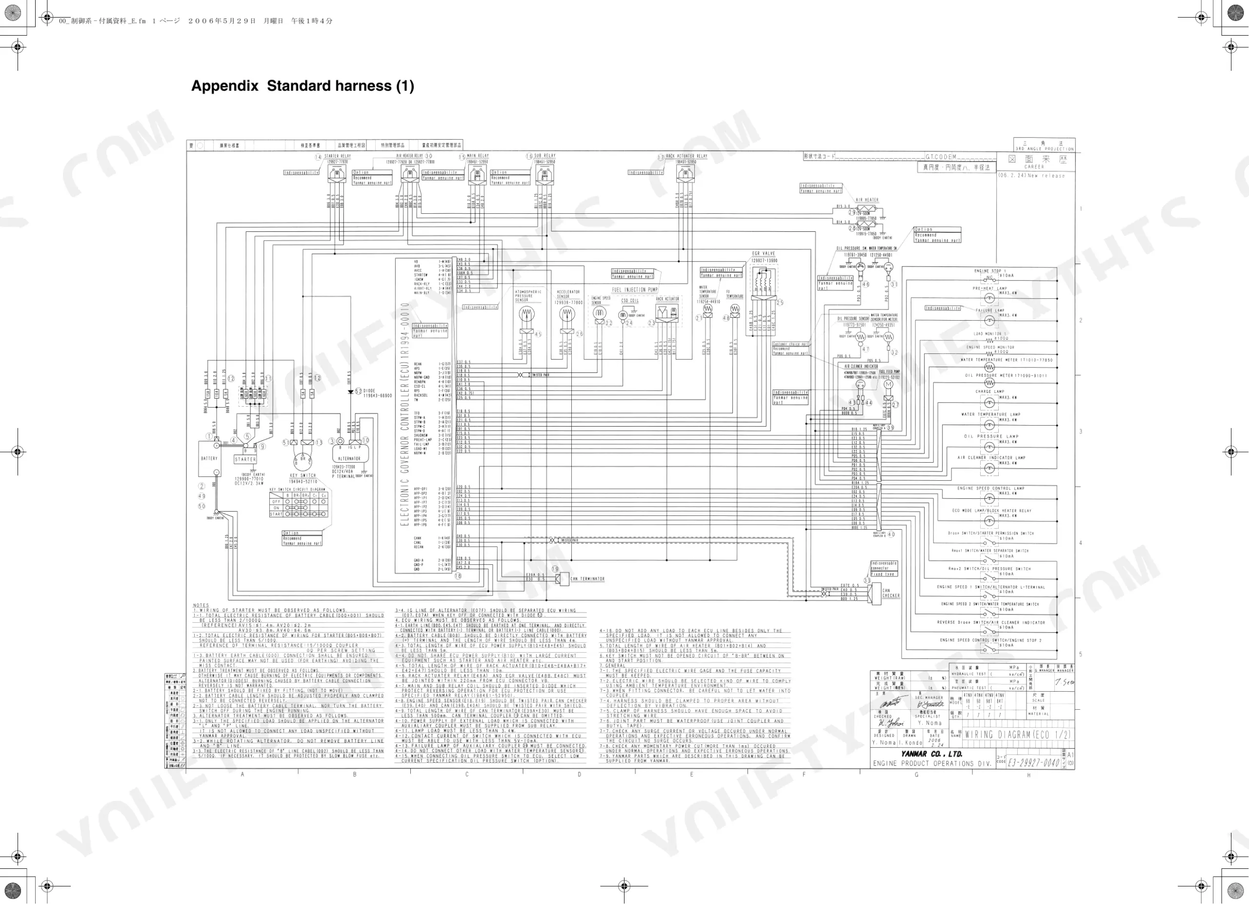
| Tnv Series Electronic Control Manual | 1-3 | Engine Control Unit, Fuel Injection Pump, EGR Valve, Accelerator Sensor, Harness, CAN Bus Termination |
| Specifications | 4-19 | Outline |
| Precautions on the Use of Electronic Control Components | 22-25 | Esd Precautions, Connector Handling, Battery Disconnect Procedure |
| Control Scheme | 26-42 | E-ECU Signal Flow, Fuel Injection Quantity Control, EGR Feedback Loop, Sensor Input Mapping |
| Harness | 43-45 | Harness Routing, Connector Pinout, Wire Gauge Specifications, Ground Points |
| Control Functions | 46-84 | Injection Quantity Control, Idle Speed Control, Overheat Protection, Dtc Detection Logic, Fuel Limit |
| Accelerator Sensor | 85-88 | EGR Valve, Fuel Injection Pump |
| Sub Relay | 89-91 | Main Relay |
| Starting Aid Relay | 92-93 | Glow Plug Relay, Cold-Start Aid Circuit, Preheat Timer Control, Starting Aid Activation |
| Coolant Temperature Sensors | 94-95 | Coolant Temperature Sensor Specs, Overheat Threshold, E-ECU Temperature Input Signal |
| Appendix Standard Harness | 96-97 | Harness Design Requirements, Harness Clamping, CAN Bus Termination |
| Tnv Series Service Tool Operation Manual | 98-100 | Fault Code, Freeze Frame Data, Diagnostic Test, Data Logging, ECU Identification, System Installation |
| Overview | 101 | Service Tool Introduction, Supported ECU Models |
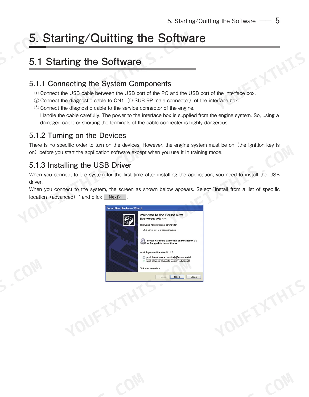
| Installing the Software | 102-103 | System Components, Devices, Usb Driver, Startup Screen |
| Description of the System | 104 | Description of the Program |
| Starting/Quitting the Software | 105-110 | Starting the Software, Quitting the Software |
| Screen Components | 111-115 | Basic Screen, Standard Tool Bar, Operation Tool Bar, Function Select Tool Bar |
| Main Menu | 116-152 | System Information, Fault Code, Freeze Frame Data, Diagnostic Test, Data Logging, Historical Data, ECU Identification, System Installation |
| Graph Function | 153-156 | Setting the Graphs, Graph Operations |
| Print Function | 157 | Print Screen, Print Data Log |
| Tool Functions | 158-160 | System Setting, User Management, Changing a Password |
| Glossary | 161 | Block Size, Controller Area Network, Diagnostic Trouble Code, Engine Control Unit, Freeze Flame Data, Failure Mode Identifier |
| References | 162 | Applicable Models Reference, Regulatory Standards |
Quick Reference Specifications
| Specification | Value | Page |
|---|---|---|
| All Models | ||
| Fuel injection pump ambient temperature limit | not exceed 80°C | p. 23 |
| Fuel injection pump replacement data | specific injection quantity data (to update E-ECU memory) | p. 23 |
| Injector pump data/reprogramming item: Correction information | Pump injection quantity correction value | p. 49 |
| Accelerator sensor rated voltage | 5 Vdc±0.01V | p. 88 |
| Accelerator sensor total resistance (sensor alone) | 5 ± 1.5kΩ | p. 88 |
| E-ECU operating ambient temperature | -30°C ~ 80°C | p. 30 |
| E-ECU storage ambient temperature | -40°C ~ 110°C | p. 30 |
| E-ECU Rated Voltage | 12 Vdc | p. 30 |
| 3TNV82A-Z | ||
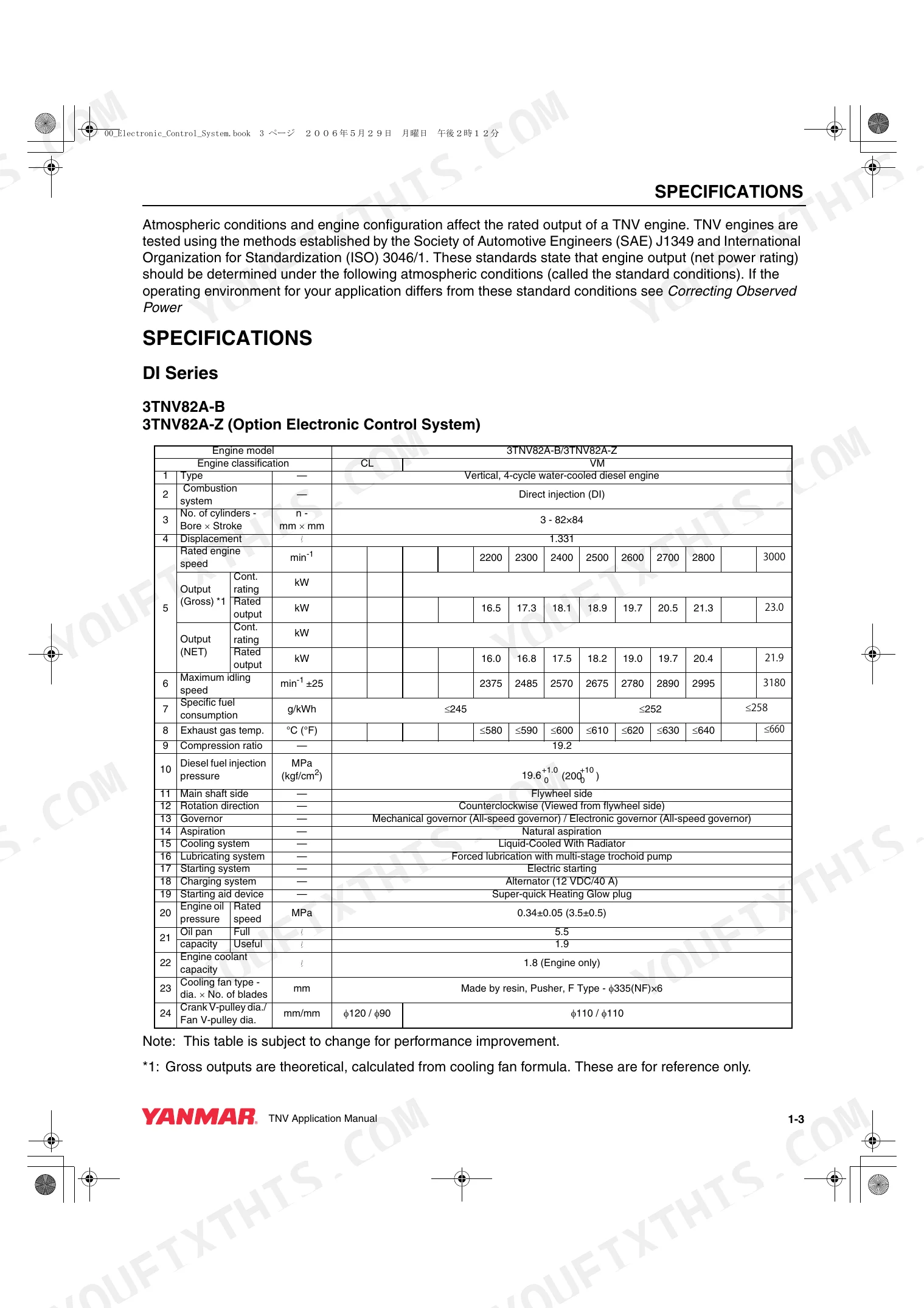
| Engine Displacement | 1.331 L | p. 6 |
| 3TNV84T-Z | ||
| Engine Displacement | 1.496 L | p. 7 |
| 4TNV88-Z | ||
| Engine Displacement | 2.189 L | p. 11 |
| 4TNV98-Z(R80-7A) | ||
| Engine Displacement | 3.318 L | p. 13 |
Yanmar Yanmar TNV Series (R55/R80-7A) Common Problems This Manual Covers
Yanmar TNV Series engine cranks but will not start or turns over very slowly in cold weather
Test the starter relay load circuit. Verify the relay maintains a rated load current of 40 A min (30 sec) during cranking as specified on page 40. Inspect the E-ECU voltage drops; ensure the minimum operating voltage does not fall below 6.0 Vdc to keep the controller active.
Manual Section: Control System p. 40Engine runs poorly or lacks power immediately after replacing the main fuel injection pump
Transfer the pump injection quantity correction value to the E-ECU using your service tool as outlined on page 49. Verify the controller receives a steady 12 Vdc base supply before flashing. Failing to reprogram the injection data will leave the engine permanently derated.
Manual Section: Control System p. 49Rough idle and highly erratic engine speed control during normal machine operating conditions
Measure the rack position sensor output. Verify the signal stays strictly within the 0 to 5V range as shown on page 35. Check the wiring harness for shorts or high resistance that could skew the voltage, forcing the E-ECU to miscalculate the required fuel delivery.
Manual Section: Control System p. 35Dead throttle pedal response or check engine lamp flashing with complete drivability loss
Inspect the accelerator sensor circuit using a multimeter. Confirm the rated supply voltage is exactly 5 Vdc ± 0.01V at the connector pins according to page 88. Replace the sensor assembly if the total internal resistance falls outside the 5 ± 1.5kΩ specification.
Manual Section: Control System p. 88Frequently Asked Questions
How do I reset the Yanmar TNV engine controller or alarm light?
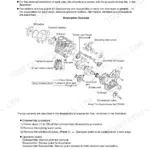
The manual describes initialization of the E-ECU at first power-up, where the failure lamp illuminates to indicate completion. For subsequent power-ups, the failure lamp illuminates for two seconds and then goes out for normal operation. If a communication error occurs or the system power is turned off, restarting the program or disconnecting/reconnecting the diagnostic connector can initialize the CPU and restore system operation. p. 33
What does error code on a Yanmar 3TNV/4TNV engine mean?
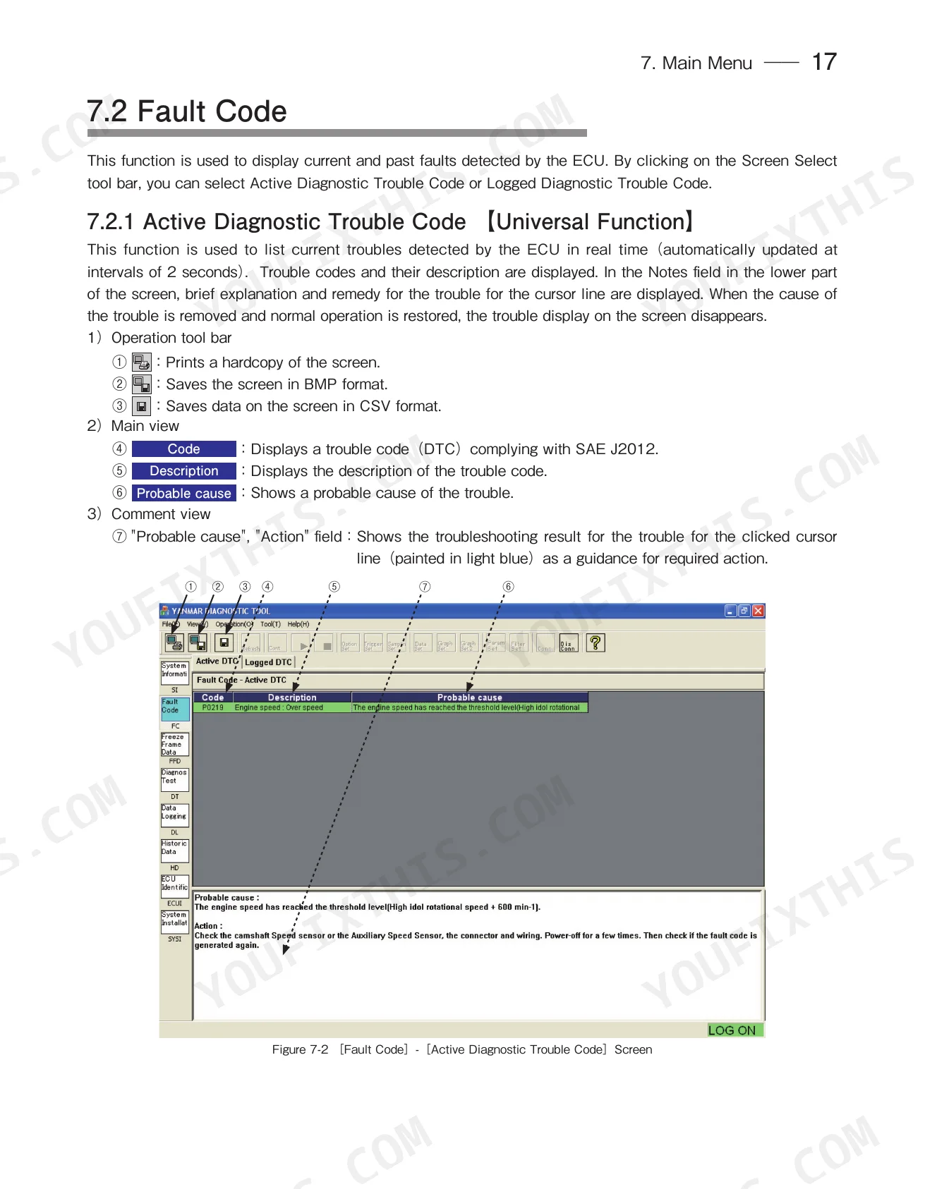
Error codes, also known as Diagnostic Trouble Codes (DTCs) complying with SAE J2012, indicate current or logged troubles detected by the ECU. The diagnostic tool displays the code, a description of the trouble, and a probable cause, along with a brief explanation and remedy in the Notes field. This information is updated automatically at intervals of 2 seconds for active codes. p. 117
How do I clear a fault code on a Yanmar TNV engine?
To clear a fault code on a Yanmar TNV engine, open / go to the "Logged Diagnostic Trouble Code" screen in the service tool. Here, you can check the "Clear" field for specific data items you wish to delete, then click the "CLEAR Logged DTC" button to remove them from the ECU's nonvolatile memory. p. 118
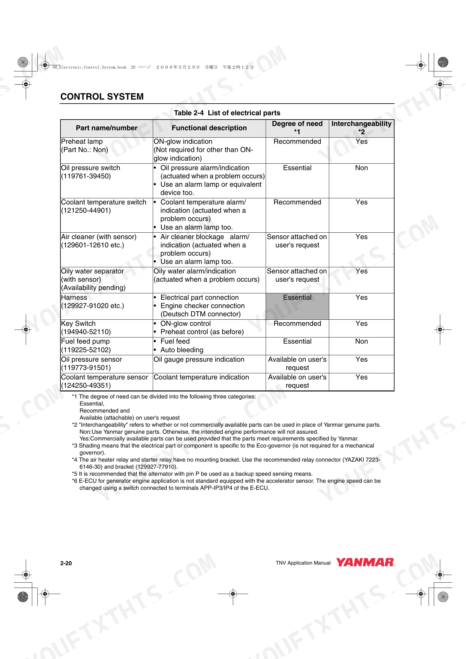
What is the oil pressure warning on a Yanmar TNV engine?
The Yanmar TNV engine uses an oil pressure switch (Part No. 119761-39450) to provide an oil pressure alarm or indication when a problem occurs. If the oil pressure switch fails to turn off while the engine is running, the E-ECU detects an "Oil pressure low" failure, which may cause the engine to run normally (depending on options) and trigger a failure lamp flash (3-1 times). p. 39
How will I receive this Yanmar 3TNV84T-Z & variants Electronic Control Manual?
You get a 162-page searchable PDF that downloads instantly after checkout. Open it on your laptop, tablet, or phone, and bring it right to the shop floor.
Is this Yanmar 3TNV84T-Z & variants Electronic Control Manual printable?
Absolutely. No DRM or copy protection. Print the whole manual or just the pages you need. Any home or office printer works.
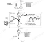
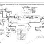
Are there wiring harness diagrams in this Yanmar 3TNV84T-Z & variants manual?
Yes, this Yanmar 3TNV84T-Z & variants Electronic Control Manual includes a wiring diagram for the electrical system.

Reviews
There are no reviews yet.