


Part of the Yanmar Parts Manuals.
All 225 pages of this official parts catalog pdf lock in the exact factory numbers needed to rebuild your 1997-2000 Crawler Backhoe. You get crystal-clear exploded views breaking down the entire machine, from the fuel tank assembly and PTO kit right down to the compressor and V-pulley setup. Open the file to find factory wiring diagrams alongside detailed component lists for the hydraulic oil tank, radiator, and complete boom assembly. Match your replacement parts to the factory baseline, verifying the 88 x 90 mm engine bore and stroke or the 4.8 / 2.3 km/h high-low travel speeds before placing an order. Stop buying the wrong components from generic aftermarket suppliers. This bookmarked PDF opens instantly on your phone or tablet so you can cross-reference part numbers directly at the machine.
What's Inside This Yanmar VIO50-1 Parts Manual
| System | Pages | Key Topics |
|---|---|---|
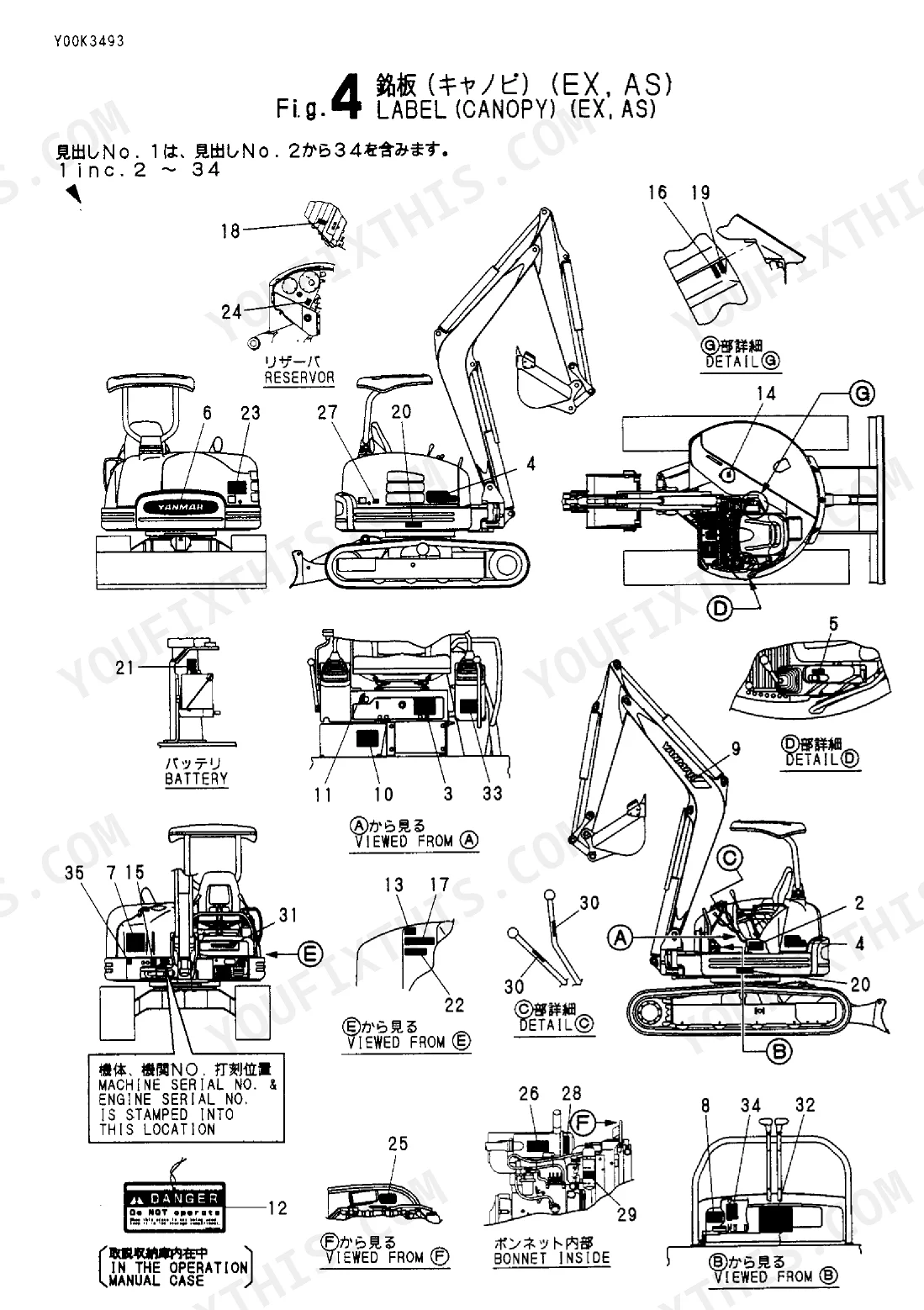
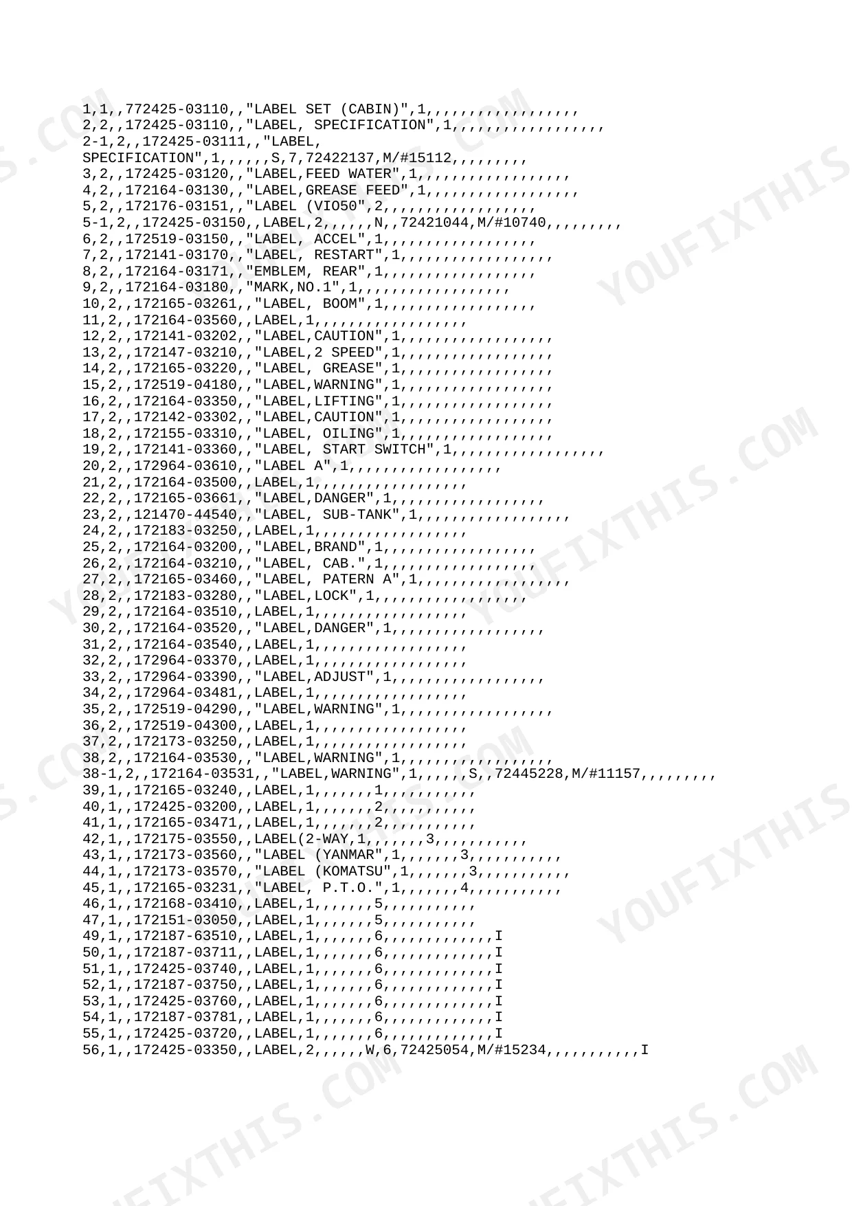
| Safety Label | - | Label Set, Specification, Warning, Caution Labels |
| Tool | - | Bag, Driver, Screw, Wrench, Filter, Turning Handle, Pliers 200 |
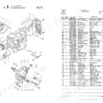
| PTO Kit | - | P.T.O. Control, Hyd. Oil Piping (P.T.O. Frame End), Hyd. Oil Piping (P.T.O. Arm End) |
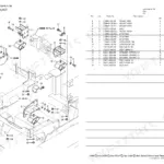
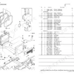
| Radiator & Oil Cooler | - | Hose a, Mount, Radiator, Sub-Tank Assy, Oil Cooler, Clamp, Radiator Hose |
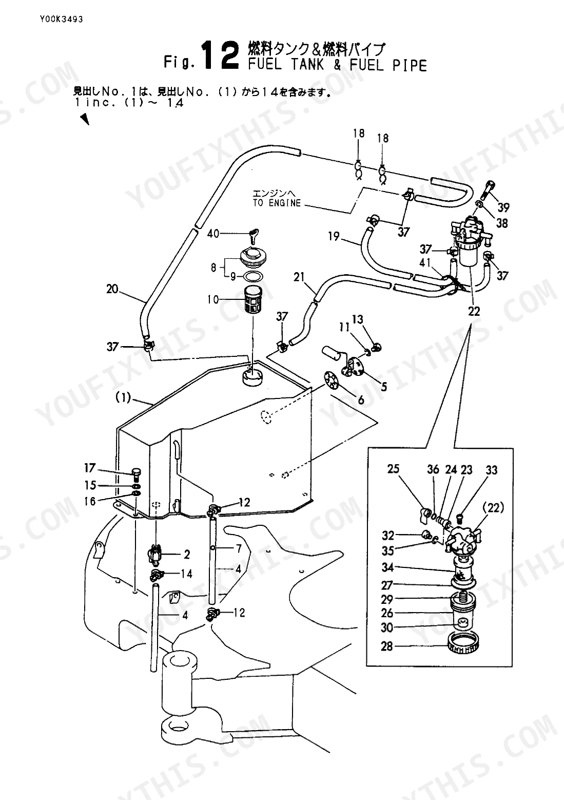
| Fuel Tank & Fuel Pipe | - | Tank Assy, Fuel Gauge Unit, Fuel Filter, Water Separator, Bowl, Fuel Strainer |
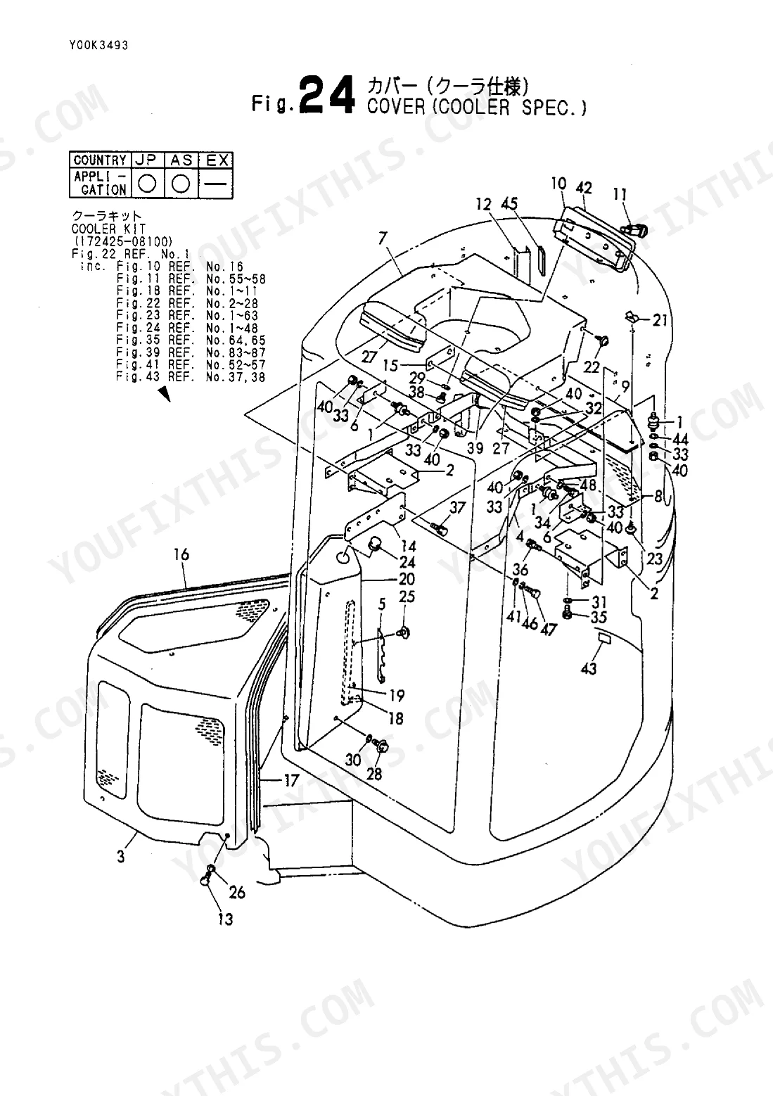
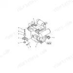
| Compressor & V Pulley (Cooler Spec) | - | Compressor, V-Belt, Pulley, Tension, Ball Bearing, Adjuster Assy |
Quick Reference Specifications
| Specification | Value | Page |
|---|---|---|
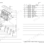
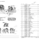
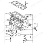
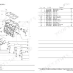
| Engine Bore x Stroke | 88 x 90 mm | p. 2 |
| Boom swing angle | Left 70 & Right 70 degree | p. 2 |
| Travel speed (High / Low) | 4.8 / 2.3 km/h | p. 2 |
Yanmar VIO50-1 Common Problems This Manual Covers
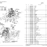
Engine loses power and runs rough indicating restricted fuel delivery or clogged fuel filter
Locate the water separator and fuel strainer part numbers in the parts catalog. Match the bowl and filter components to your specific 88 x 90 mm bore engine configuration. Confirm all part numbers against the master list before ordering replacements.
Manual Section: Fuel Tank & Fuel PipeEngine overheating under heavy load due to leaking radiator hoses or damaged oil cooler
Review the radiator mounting section to identify the correct hose and clamp part numbers. Select the proper sub-tank assembly components to maintain cooling for the 88 x 90 mm bore engine. Use the Parts Number List to verify hose and clamp compatibility.
Manual Section: Radiator & Oil CoolerLeft and right boom swing angle feels restricted or binds during heavy digging operations
Examine the Boom & Attachment Parts Diagram for boom mounting hardware. Identify the specific pivot pins and bushings required to restore the Left 70 & Right 70 degree boom swing angle. Cross-reference the identified components with the master index.
Manual Section: PTO KitFrequently Asked Questions
What are the replacement specifications for hydraulic hoses?
The manual provides replacement specifications for hydraulic hoses by listing their part numbers and descriptions in various "HYD. OIL PIPING" sections. For example, in Fig. 69 (page 166), item 10 is "HOSE H208BC189" with part number 172425-78130, and item 15 is "HOSE P206CC085S" with part number 172423-78170. Other hose specifications can be found in figures 70, 71, 72, 73, 74, 75, 76, 77, and 78. p. 166
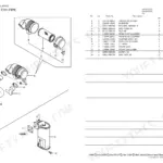
What are the replacement specifications for hydraulic seals?
The manual provides replacement specifications for hydraulic seals by listing their part numbers and descriptions within cylinder assembly sections. For instance, in Fig. 47 (page 119), item 14 is "SEAL SET, HEAD" with part number 172151-71810, and item 24 is "SEAL SET, PISTON" with part number 172151-71800. Similar seal sets are listed for other cylinders in figures 48, 49, 50, 51, and 52. p. 119
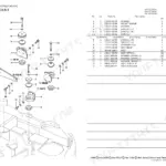
How do you fix boom lift is weak under load and need correct hydraulic seal kit part numbers?
Inspect the Hydraulic Parts Diagram for the correct seal kit part numbers. Identify the specific cylinder seals needed for the 88 x 90 mm bore engine configuration. Cross-reference your findings with the Parts Number List to order exact replacements.
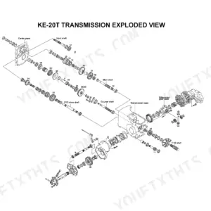
How do you fix undercarriage track looseness and slow travel speed requiring replacement final drive and sprocket parts?
Check the Chassis Parts Diagram to locate final drive components and sprockets. Verify the specific sprocket part number required to restore the 4.8 / 2.3 km/h travel speed. Order the exact idler wheels and track rollers shown in the diagram.
How quickly can I access this manual after buying?
A 225-page Parts Catalog in searchable PDF format, available the moment you complete checkout. View on computer, tablet, or phone, with no shipping wait.
Can I print specific sections of this Parts Catalog?
Yes, print as many copies as you want, and there are no restrictions. Many mechanics print the section they need and bring it to the shop floor.
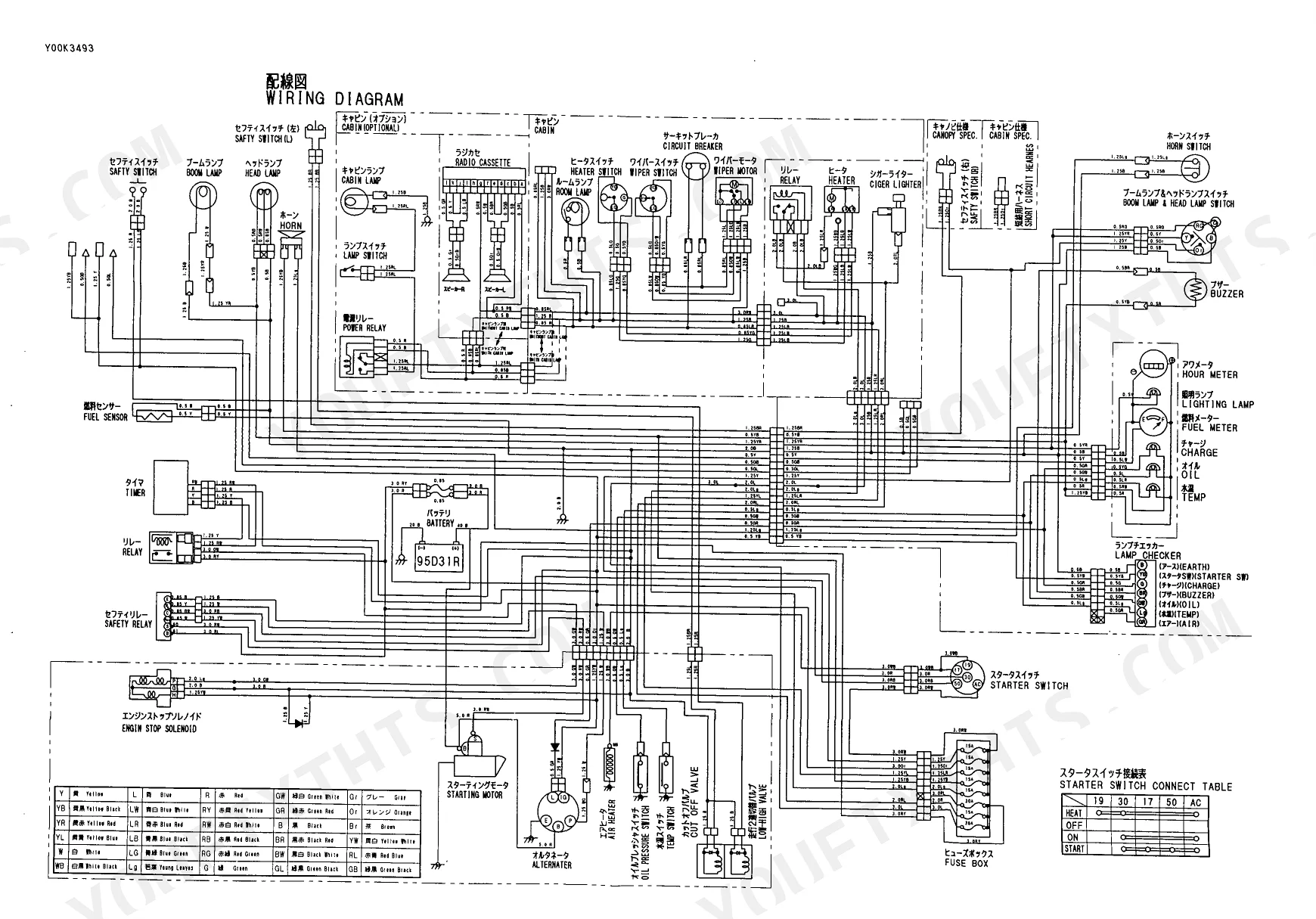
Does this manual include wiring diagrams?
Included. The Parts Catalog provides a wiring diagram for the electrical system.
Reviews
There are no reviews yet.