

Part of the Yanmar Repair Manuals.
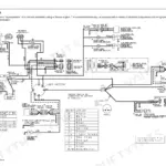
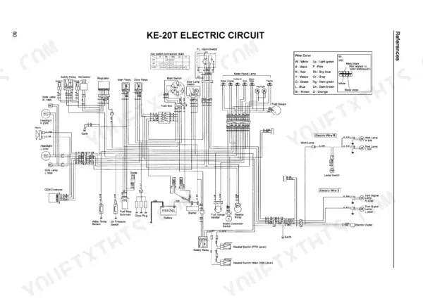
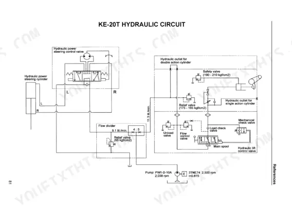
Every system on your compact tractor gets broken down to the bare bolts in this 89-page Yanmar KE-20T Technical Manual PDF. Open up detailed wiring diagrams for the preheating and charging circuits, complete hydraulic piping schematics, and full transmission exploded views. You get step-by-step teardown instructions for the clutch assembly, front axle, differential gear, and power steering valve, plus a dedicated section covering the hydraulic raising and lowering device. Dial in your clutch pedal play to exactly 15-25 mm and verify you have the correct 119853-77010 starting motor installed before tearing into the engine starting circuit. Stop guessing at adjustments and burning up expensive replacement parts. Download this bookmarked file directly to your tablet, tap the section you need, and get your tractor running right.
What's Inside This Manual
| System | Pages | Key Topics |
|---|---|---|
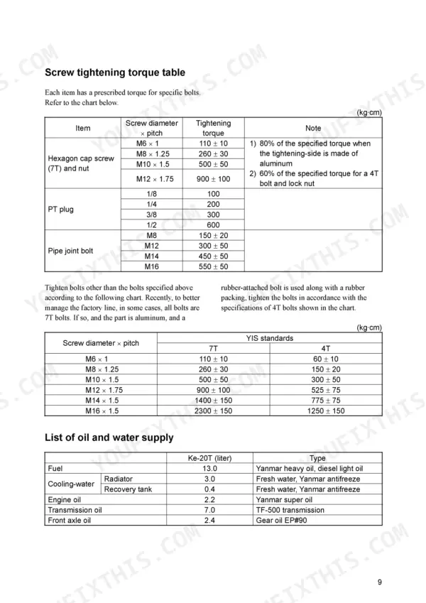
| Safety | 4-5 | Safety-Alert Symbol, Improvements, Screw Tightening Torque Table, List of Oil and Water Supply, List of Periodic Inspections |
| Precautions for the Safe Services | 6-9 | Sufficient Ventilation, Flat Place, Proper Lifting and Support, Proper Tools, Tighten Bolts and Nuts, Battery Electrolyte Handling |
| General Precautions for Services | 10 | Yanmar Genuine Parts, Packing and O-Ring, Snap Ring Installation, Spring Pin Installation, Thrust Washer, Coupler Connection |
| Usage of the Liquid Gasket | 11-12 | Paring Sealant, Applying Liquid Gasket, Liquid Gasket Deterioration |
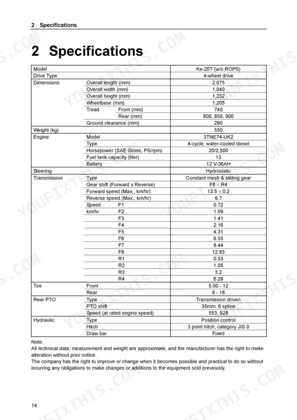
| I Outline and Specifications | 15-28 | Outline (Name of Each Part), Specifications, Engine (Outline, Fuel System, Lubrication System, Cooling Water System, List of Engine Tightening Bolts) |
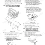
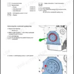
| Ii Roughly Disassembling Tractor Components | 29-36 | Removing the Clutch (Preparation, Right-Side Removal Positions, Left-Side Removal Positions, Hydraulic Piping, Clutch Housing), Removing the Front Axle, Removing the Rear Axle Case |
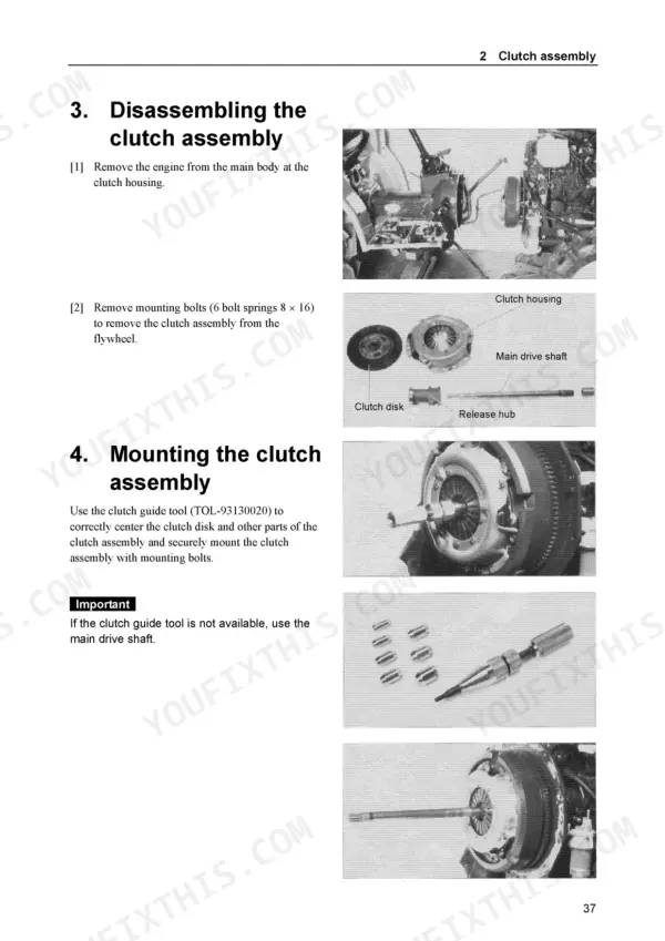
| Iii Main Body | 37-54 | Main Body Power Transmission, Clutch Assembly (Structure and Function, Adjustment Standards, Disassembling the Clutch Assembly, Mounting the Clutch Assembly, Clutch Pedal) |
| Iv Hydraulic Raising/ Lowering Device | 55-68 | Hydraulic raising/lowering Device |
| V Electrical Device | 69-83 | Engine Starting/Stop Circuit (Outline, Locations and Functions of the Components, Circuit Diagram, Electrical Component Inspection Procedures) |
| Ke-20T Electric Circuit | 84-85 | Safety Relay, Generator, Regulator, Main Switch, Battery, Starter |
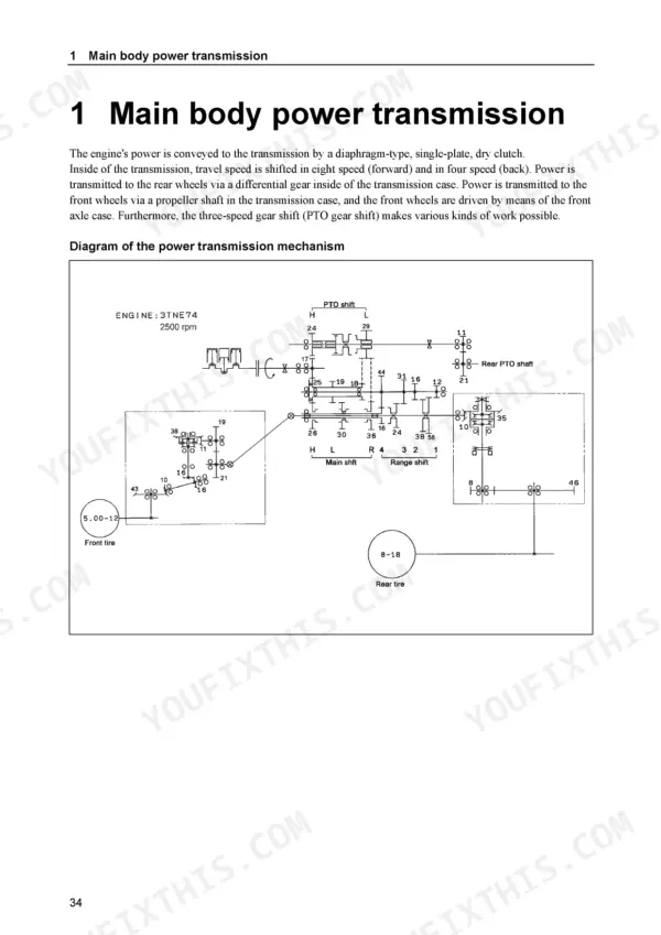
| Ke-20T Power Transmitting Diagram | 86 | Engine, PTO Shift, Rear PTO Shaft, Main Shift, Range Shift, Front and Rear Tires |
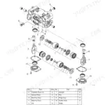
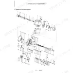
| Ke-20T Transmission Exploded View | 87 | Structure and Function, Cross-Sectional View of the Transmission, Disassembling the Transmission |
| Ke-20T Hydraulic Piping | 88 | Hydraulic Power Steering Cylinder, Front Axle Case, Flow Divider, Hydraulic Power Steering Valve, Hydraulic Pump, Hydraulic Cylinder Case |
Quick Reference Specifications
| Specification | Value | Page |
|---|---|---|
| Battery model | 55B24RL | p. 27 |
| Thermostat usage | not used | p. 25 |
| Starting motor part code | 119853-77010 | p. 27 |
| Key switch part number | 198162-52110 | p. 71 |
| Clutch Pedal Play | 15-25 mm | p. 40 |
| Steering Toe-in Value | 15-25 mm | p. 46 |
| Brake Pedal Play | 25-35 mm | p. 51 |
| Engine Head Bolt Torque (M9 x 1.25) | 6.0-6.5 kg-m | p. 28 |
| Engine Rod Bolt Torque (M7 x 1.0) | 2.3-2.8 kg-m | p. 28 |
| Generator Terminals Resistance (sb-sb) | 0.2-0.9 Ω | p. 83 |