
Part of the Yanmar Parts Manuals.
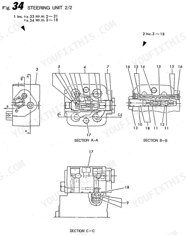
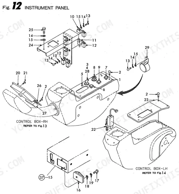
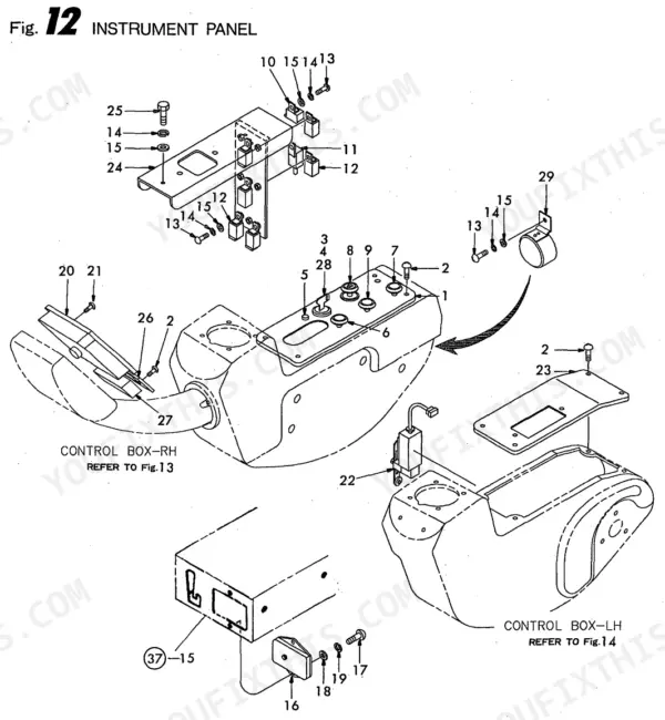
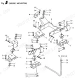
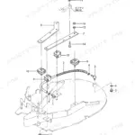
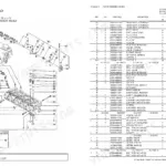
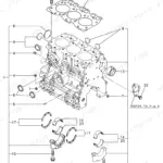
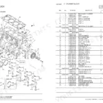
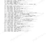
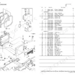
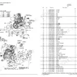
Need to identify a part on your Wheel Excavator? All 178 pages of this OEM Parts Catalog cover the machine. Exploded-view diagrams break down every major assembly: engine mounting, front and rear axle differentials, hydraulic cylinders (swing, bucket, arm, boom, blade), swing motor, main control valve, travel motor, and full cab electrical. Each diagram links to a numbered parts list so you can pinpoint a gearbox selector fork, a differential bevel gear set, or a main pump housing without guessing at compatibility. Wrong parts waste your day. Bookmarked and keyword-searchable PDF: open it on your tablet, find the assembly, pull the number, and order the right piece the first time.
What's Inside This Yanmar B50W, B50W-1, 4TN84TL-RBS, 4TNE84T-BS Parts Manual
| System | Pages | Key Topics |
|---|---|---|
| Clutch & Transmission | Transfer Gear Box Case, Gear Box Motor & Pump, Transmission Control | |
| Fuel System | Fuel Tank, Fuel Line | |
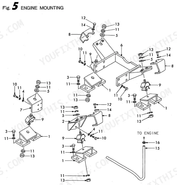
| Engine | Engine Control System, Engine Mounting | |
| Electrical System | Battery Install, Cabin Electrical | |
| Rear Axle, Differential & Brakes | Front Axle Case, Front Brake Disc, Rear Axle Housing, Rear Differential Carrier, Rear Axle Case, Rear Brake Disc, Brake Cylinder Assembly, Lower Brake Install | |
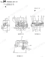
| Front Axle & Steering | Front Axle Housing, Front Differential Carrier, Steering Cylinder, Steering Wheel & Column, Steering Unit | |
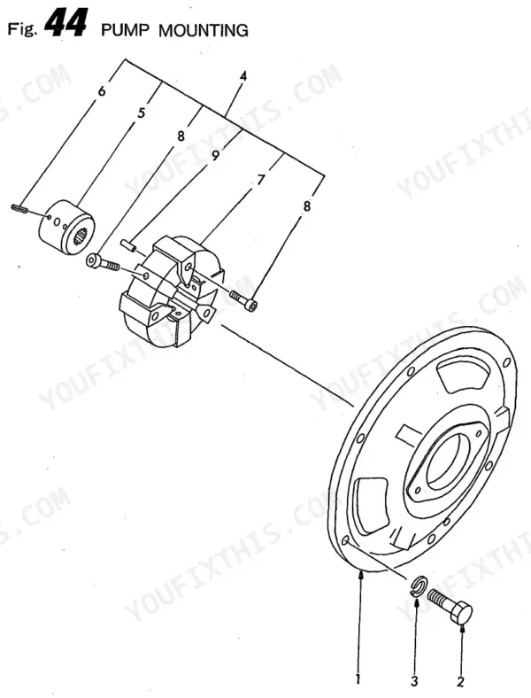
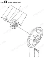
| Hydraulics & 3-Point Hitch | Pump Mounting, Main Pump Assy, Swing Cylinder Assembly, Bucket Cylinder Assembly, Arm Cylinder Assembly, Blade Cylinder Assembly, Boom Cylinder Assembly, Axle Locking Cylinder Assembly, Swing Motor, Main Control Valve, Rd Valve, Hydraulic Tank Install, Attachment Piping, Breaker Piping, Main Piping, Upper Piping | |
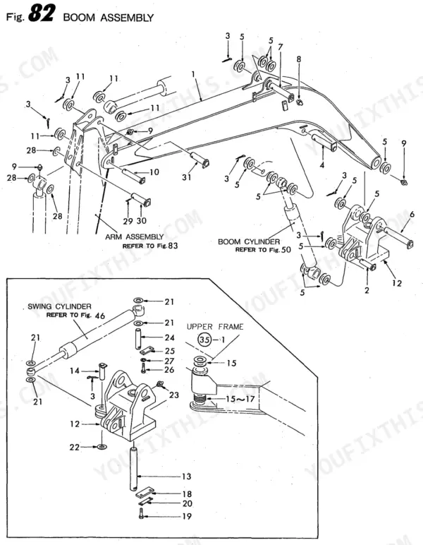
| Loader, Backhoe & Attachments | Swing System, Rotary Group, Boom Assembly, Blade, Bucket & Connecting Rod | |
| Body & Operator Station | Rear View Mirror, Instrument Panel, Heater & Defrost Mounting, Upper & Lower Frame, Floor & Bottom Plate, Bottom Cover, Bonnet Install, Cabin Install | |
| Decals & Accessories | Label | |
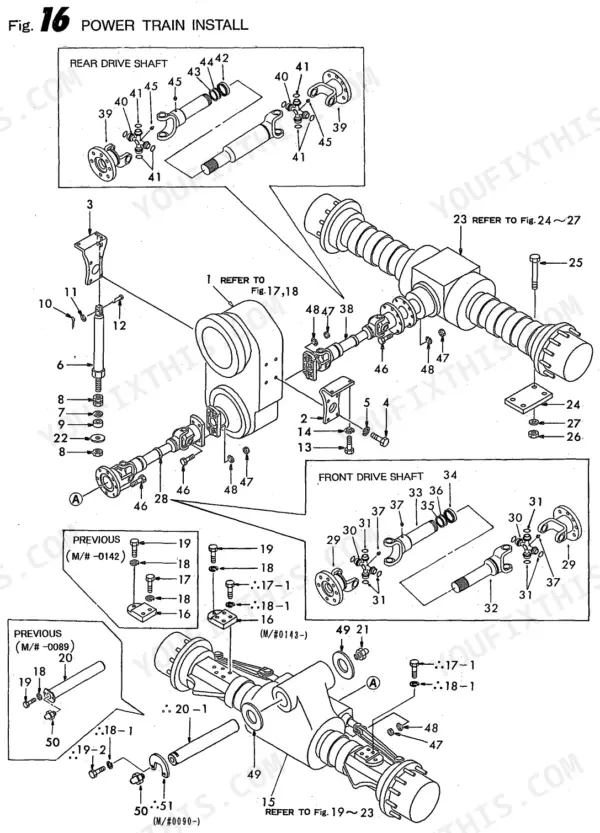
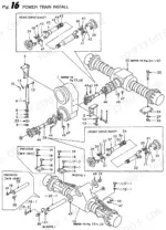
| Other Components | Intake & Exhaust System, Control Box, Power Train Install, Wheel Rim & Tire, Control Link Install, Control, Turning Joint, Arm Assembly |
Quick Reference Specifications
| Specification | Value | Page |
|---|---|---|
| B50W / B50W-1 Wheel Excavator | ||
| 4TN84TL-RBS / 4TNE84T-BS | ||
| Parts Catalog | ||
| 178 | ||
| Y00S3381 | ||
| See p.165 (Boom Assembly, Seal Kit line item) | ||
| E804800580 (p.92, Swing Cylinder) | ||
| E945900900 / E947603708 (p.124) |
Yanmar B50W, B50W-1, 4TN84TL-RBS, 4TNE84T-BS Common Problems This Manual Covers
Yanmar B50W boom cylinder seal kit hard to identify, exploded view shows piston, gland, and rod components separately
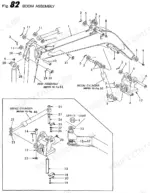
Open the Boom Cylinder Assembly section. Find the Seal Kit line item in the exploded view on page 165, listed alongside the Tube Weld, Rod Weld, Gland, and Piston. Order the Seal Kit as one assembly rather than individual seals. Cross-reference against the parts number list on page 2 to confirm the correct part number for your serial number range.
Manual Section: Boom Cylinder Assembly p. 165Hydraulic pump part numbers confusing, main pump and gear pump listed as overlapping sub-assemblies
Turn to the Pump Mounting section, then to Main Pump Assy. On page 89 the exploded view breaks out the Main Pump, Gear Pump, and Horn Type Pump as individual orderable assemblies. Order each as a complete unit or by sub-component. Verify the pump housing part number on page 2 first, since housing variants differ between B50W and B50W-1.
Manual Section: Main Pump Assy (INC.PUMP,HORN T) p. 89Wiring harness replacement part number unclear, instrument panel fuse box and relay positions not labeled in diagram
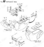
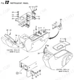
Go to the Electrical System section for the main wiring harness part number, then to Instrument Panel for the fuse box, relay, and key starter numbers. Locate each component in the cab interior diagram on page 25. Record the balloon number from the exploded view, then verify the part number in the index on page 2 before ordering.
Manual Section: Electrical System p. 25Bucket tooth and side blade replacement parts scattered across diagram, can't confirm which tooth fits
Check the Bucket & Connecting Rod section for tooth and blade side part numbers. The attachment diagram on page 165 shows the complete bucket assembly with individual tooth positions called out by balloon number. Verify the bucket assembly number on page 2 first, as tooth profiles vary between bucket configurations. Order the blade side and tooth as separate line items.
Manual Section: Bucket & Connecting Rod p. 165Front axle differential carrier bevel gear set and shim selection unclear from exploded view
Open the Front Differential Carrier section. The drivetrain diagram starting on page 33 shows the Case Axle, Grub Bolt, Grease Fitting, Pivot Pin, and Shim as individual line items. Cross-reference each Shim position number against the parts index on page 2 to identify available thickness options. Verify the Front Axle Housing assembly number before ordering any bevel gear components.
Manual Section: Front Differential Carrier p. 33Fuel tank strainer and drain cock part numbers scattered, correct cap assembly hard to locate in catalog
Look in the Fuel Tank section. The Strainer, Cap, Drain Cock, Gauge Hose, and Clamp each appear as separate line items in the exploded view. Find the engine area diagram on page 11 to locate the tank and its fittings in context. Pull each balloon number, then confirm the corresponding part number in the index on page 2 before ordering.
Manual Section: Fuel Tank p. 11Frequently Asked Questions
What are the replacement specifications for Hydraulic hoses?
The manual lists various hydraulic hoses with their respective part numbers and quantities. For example, on page 124, part number E945900900 is for a "HOSE" with a quantity of 1, and E947603708 is also for a "HOSE" with a quantity of 1. On page 136, part number E948201212 is for "HOSE ASSY,GREASE 3.6" with a quantity of 2. p. 124
What are the replacement specifications for Hydraulic seals?
The manual provides part numbers and some dimensional specifications for hydraulic seals. For instance, on page 92, part number E804800580 is for a "KIT,SEAL" with a quantity of 1, and E956410400 is for a "WIPER,DUST 40X 10" with a quantity of 1. Additionally, E951122090 is an "O-RING G90" with a quantity of 1. p. 92
How do you fix boom cylinder seal kit hard to identify, exploded view shows piston, gland, and rod components separately?
Open the Boom Cylinder Assembly section. Find the Seal Kit line item in the exploded view on page 165, listed alongside the Tube Weld, Rod Weld, Gland, and Piston. Order the Seal Kit as an assembly rather than individual seals. Cross-reference against the parts number list on page 2 to confirm the correct part number for your serial number range. p. 165
How do you identify hydraulic pump part numbers when the main and gear pump sub-assemblies overlap in the catalog?
Turn to the Pump Mounting section, then to Main Pump Assy. On page 89 the exploded view breaks out the Main Pump, Gear Pump, and Horn Type Pump as individual orderable assemblies. Order each as a complete unit or by sub-component. Verify the pump housing part number on page 2 first, since housing variants differ. p. 89
What do I get after purchasing this Wheel Excavator Parts Catalog?
Instant PDF download. You get the full 178-page searchable Parts Catalog immediately after payment. Open it on your laptop, tablet, or phone right in the shop.
Can I print specific sections of this Wheel Excavator Parts Catalog?
Yes. Print individual pages or full chapters for your own shop use, on letter or A4 paper.




Reviews
There are no reviews yet.