


Part of the Case Repair Manuals.
All 220 pages of this Case 686G Service Manual (OEM #7-89650) focus on one machine family: the 686G and 686G XR telescopic handlers, from engine bay to boom tip. Inside, you get full electrical schematics covering the console and enclosed cab option, a complete hydraulic schematic with fluid routing through the boom control valve, frame leveling circuit, and joystick assembly, plus a troubleshooting section hitting every major system: engine, steering, powershift transmission, brakes, hydraulic pump, and boom. Packed with exploded views and step-by-step rebuild procedures for every cylinder in the machine. Torque the crowd cylinder piston locknut to 1492-1763 Nm and the boom lift cylinder piston locknut to 1898-2305 Nm — exact factory numbers, right here. Your telehandler is down and the clock is running. Grab this PDF, search any spec by keyword, bookmark any section, and get back under the boom.
What's Inside This Case 686G, 686G XR, 686GXR Manual
| System | Pages | Key Topics |
|---|---|---|
| General | 3-22 | Safety Information (Understanding Signal Words), Engine Safety, Electrical Safety |
| Engine | 23-40 | Type, Horsepower, Oil, Normal Operating Temperature, Low Idle Speed, High Idle Speed |
| Fuel System | 41-46 | Fuel System and Filters, Specifications (Diesel Fuel, Fuel Storage, Acceptable No. 2 Diesel Fuel) |
| Electrical System | 47-62 | Electrical System Specifications, Electrical Schematic, Troubleshooting, Gauges and Senders, Alternator, Starter |
| Steering System | 63-90 | Steering Control Valve, Steering System Specifications, Troubleshooting, Removal and Disassembly (Remove Steering: Wheel, Control Valve) |
| Power Train | 91-114 | Transmission, Powershift Transmission Specifications, Low Clutch Pressure, Low Charging Pump Output, Overheating, Noisy Converter, Lack of Power, Axle Specifications |
| Brakes | 115-134 | Brake System, Brake System - How It Works (General, Operation), Brake System Specifications, Brake Valve (Removal, Disassembly, Assembly, Installation) |
| Hydraulics | 135-186 | Hydraulic System |
| Mounted Equipment and Chassis | 187-218 | Mounted Equipment (Frame Leveling Circuit, Boom Assembly, Crowd Cylinder), Boom Specifications, Troubleshooting, Boom, Boom Components Removal and Installation |
| Electrical and Hydraulic Schematic | 219-220 | 686G and 686GXR Telehandler Electrical Schematic, Console, Enclosed Cab Option, 686G and 686GXR Telehandler Hydraulic Schematic |
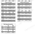
Quick Reference Specifications
| Specification | Value | Page |
|---|---|---|
| Crowd Cylinder Piston Locknut Torque | 1492 to 1763 Nm (1100 to 1300 lb-ft) | p. 173 |
| Boom Lift Cylinder Piston Locknut Torque | 1898 to 2305 Nm (1400 to 1700 lb-ft) | p. 175 |
| Park Brake Solenoid Mounting Nut Torque | 5 - 8 Nm (4 - 6 lb-ft) | p. 166 |
| Park Brake Solenoid to Cartridge Nut Torque | 5 - 8 Nm (4 - 6 lb-ft) | p. 167 |
| Load Sensing (LS) Adjustment Seal Lock Nut Torque | 23 Nm (17 lb-ft) | p. 164 |
Case 686G, 686G XR, 686GXR Common Problems This Manual Covers
Case 686G telescopic handler boom won't extend or retract, no movement at joystick
Inspect the boom extension solenoid wiring and connectors for corrosion or broken terminals at the valve body. Check the hydraulic schematic on page 219 to trace the boom circuit. If pressure is present but the boom is still unresponsive, clean and reset the load sensing circuit; retorque the LS adjustment lock nut to 23 Nm (17 lb-ft) per page 164.
Manual Section: Hydraulic System Troubleshooting p. 173Boom settles or creeps downward slowly when held in elevated position under load
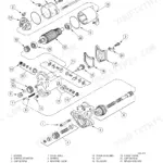
Lower the boom fully and relieve system pressure before disassembly. Remove the boom lift cylinder, inspect piston seals for wear or bypassing, and replace any damaged components. Reinstall the piston and torque the locknut to 1898 to 2305 Nm (1400 to 1700 lb-ft) as specified on page 175. Retest under full rated load after reassembly.
Manual Section: Boom TroubleshootingHydraulic fluid leaking from crowd cylinder rod end or carriage tilt cylinder seals
Clean and dry the cylinder exterior to confirm the leak source. Depressurize the system, remove the cylinder, and disassemble the rod end. Replace O-rings, wiper seals, and piston seals as a complete kit. Reinstall the piston and torque the locknut to 1492 to 1763 Nm (1100 to 1300 lb-ft) per page 173 for the crowd cylinder.
Manual Section: Hydraulic System Troubleshooting p. 173Frame leveling loses position on slopes, machine tilts slowly while sitting stationary
Inspect the frame level cylinder check valve for dirt or wear. Depressurize the system and remove the cylinder. Clean the check valve seat and install a new cartridge, torquing to 41 to 47 Nm (30 to 35 lb-ft) per page 181. Cycle the leveling circuit after reassembly and verify the cylinder holds position on uneven ground.
Manual Section: Mounted Equipment and Chassis p. 187Park brake drags or won't release fully, machine hard to move with brake disengaged
Inspect the park brake solenoid wiring and check for voltage at the solenoid connector with the brake control energized. If the solenoid moves but the brake still drags, remove and clean the cartridge. Install a new solenoid and secure with the mounting nut torqued to 5 to 8 Nm (4 to 6 lb-ft) per page 166.
Manual Section: Brakes p. 115Frequently Asked Questions
Torque specs for
The engine mounting plates (13) are attached to the engine (1) with cap screws (15) and tightened to 150 Nm (111 lb-ft). The lower half of the engine shock mount (12) is tightened to 570 Nm (420 lb-ft). Transmission mounting bushings (7) are tightened to 814 Nm (600 lb-ft). p. 35
Is this Case 686G, 686G XR, 686GXR Service Manual a digital download?
You get a 220-page searchable PDF (17 MB) that downloads instantly after checkout. Open it on your laptop, tablet, or phone, and bring it right to the shop floor.
Can I print specific sections of this Case 686G, 686G XR, 686GXR Service Manual?
No restrictions at all. Print individual pages, full chapters, or the entire manual. The PDF is completely unlocked.
Are there hydraulic schematics in this Case 686G, 686G XR, 686GXR manual?
Yes. The manual includes hydraulic circuit diagrams, system schematics, and component specifications with pressure ratings.


Reviews
There are no reviews yet.