


Part of the Case Repair Manuals.
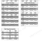
All 260 pages of this Case CK36 / CK50 Service Manual zero in on one job: returning your mini excavator to factory spec, whether you're working on a CK36 or the larger CK50. Inside you get complete wiring schematics and full hydraulic circuit diagrams covering both models, a travel motor and swing reduction teardown sequence, plus a dense troubleshooting section that walks you through pressure-setting procedures and hydraulic fault diagnosis step by step. Torque tables run throughout: cylinder head bolts seat at 93.2–98.1 N·m, and standard M6 fasteners range from 7.8 N·m (Grade 4) up to 12.3 N·m (Grade 9) — no guessing, no cross-referencing a generic chart. Your machine is down and forum posts won't fix it. Pull up the factory answer: bookmarked by system, searchable by keyword, readable on any device you bring to the machine.
What's Inside This Case CK36, CK50 Manual
| System | Pages | Key Topics |
|---|---|---|
| Safety, General Information and Specifications | 3-27 | Safety Instructions, Standard Fastener Torque Specifications, Hydraulic Connection Torque Specifications, Product Identification and Serial Numbers, Hydraulic Specifications (CK36), Hydraulic Specifications (CK50), Electrical Specifications, Tracks, Rollers and Idlers (CK36) |
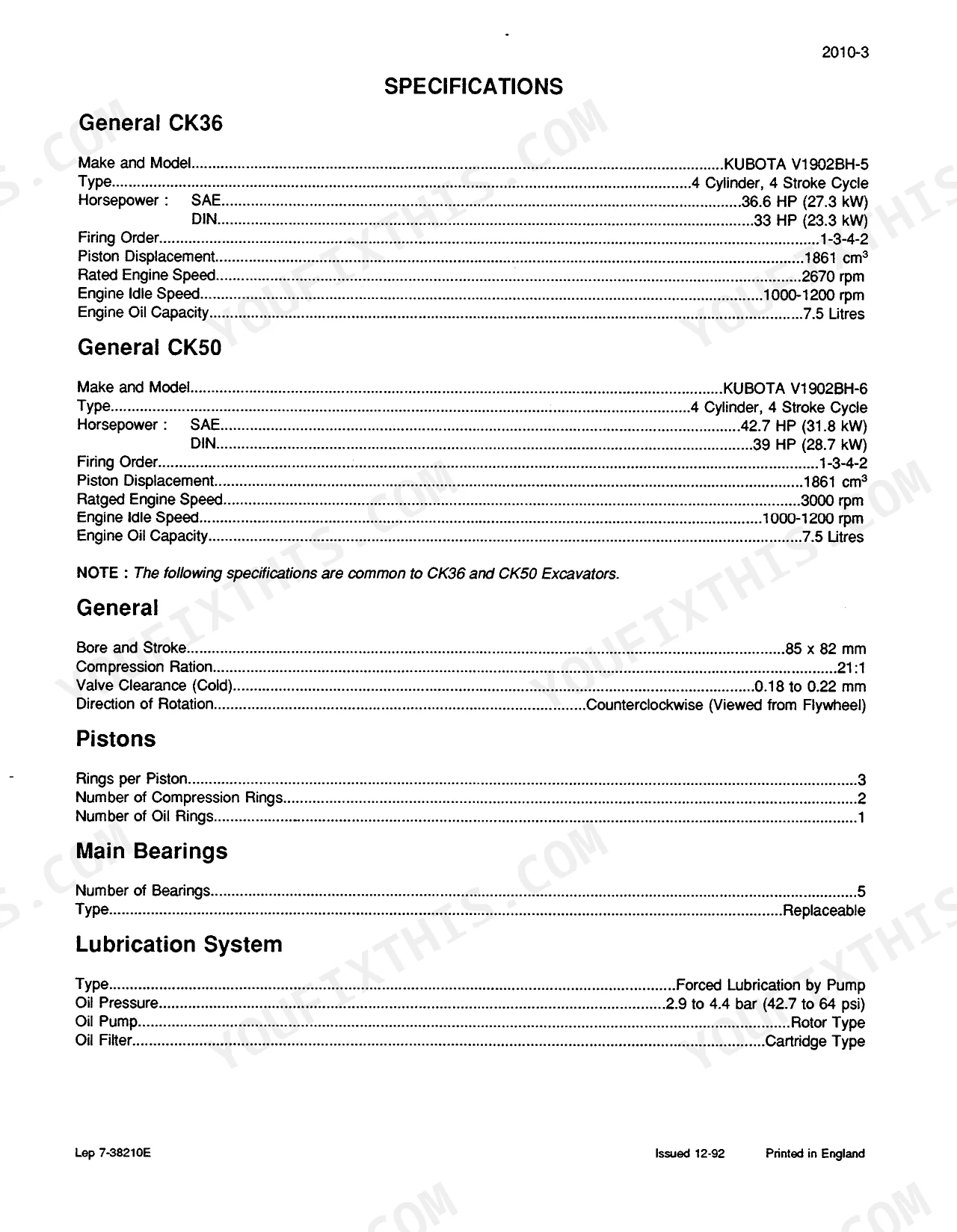
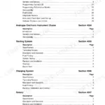
| Engine System (Removal, Overhaul, Electrical) | 28-58 | Engine Removal and Installation, Cylinder Head, Timing Gear and Camshaft, Pistons, Conrods and Crankshaft, Alternator, Starter Motor, Electrical Troubleshooting and Schematics |
| Undercarriage and Travel Motor | 59-94 | Rubber Track, Idler Wheel, Cylinder Block, Lubrication System, Cooling System, Fuel System, Travel Motor and Reduction, Cross Sectional Drawing of the Reduction Motor, Cross Sectional Drawing of the Speed Limiter |
| Swing Reduction Gear and Hydraulic Swivel | 95-104 | Swing Reduction Gear, Hydraulic Swivel, Hose Connections, Removal and Installation, Disassembly and Assembly |
| Hydraulic Pressure, Reservoir and Pumps | 105-134 | CK36/CK50 Troubleshooting, CK36/CK50 Pressure Setting Schematic, CK36/CK50 Pressure Settings, Hydraulic Reservoir, Hydraulic Pump, Pilot Controlled Hydraulic Pump |
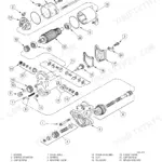
| Attachment and Flow Control Valves | 135-154 | Parts Designations (CK36), Parts Designations (CK50), Primary Control Valve and Relief Valve (CK36), Primary Control Valve and Relief Valve (CK50), Swing and Offset Cylinder Flow Selector Valve, Pressure Limiter and Flow Cut-Off Valve, Hose Connections |
| Swing Motor and Hand Control Valve | 155-168 | Swing Motor, Hand Control Valve, Cross Sectional Drawing, Disassembly and Assembly of Plunger Assembly, Removal and Installation, Inspection |
| Attachment Cylinders | 169-186 | Boom Cylinder, Dipper Cylinder, Bucket Cylinder, Offset Cylinder, Levelling Blade Cylinder (CK36), Specifications (CK36), Specifications (CK50) |
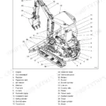
| Upperstructure and Turntable Bearing | 187-192 | Turntable Bearing Assembly Specifications, Removal and Installation, Inspection |
| Boom, Dipper, Bucket and Levelling Blade | 193-204 | Bucket, Dipper, Offset Support, Boom and Levelling Blade, Checks |
| Pedals and Levers | 205-216 | L.H. Travel Control Lever, R.H. Travel Control Lever, Engine Throttle Cable, Safety Lock Lever, Dozer Blade Control Lever, Second Speed Control Pedal |
| Operator's Cab and Canopy | 217-260 | Canopy, Cab, Removal, Installation |
Quick Reference Specifications
| Specification | Value | Page |
|---|---|---|
| M6 Standard Fastener Torque (Grade 4) | 7.8 to 9.3 Nm (5.75 to 6.86 lb ft) | p. 6 |
| M6 Standard Fastener Torque (Grade 7) | 9.8 to 11.3 Nm (7.23 to 8.33 lb ft) | p. 6 |
| Rocker Cover Retaining Nuts Torque | 6.9 to 8.8 Nm | p. 26 |
| Cylinder Head Bolts Torque | 93.2 to 98.1 Nm | p. 26 |
Case CK36, CK50 Common Problems This Manual Covers
Machine won't swing or swings jerkily, upper structure rotation is grinding or hesitating
Drain and inspect the swing motor on page 155 — check pistons and valve plate surfaces for scoring. Remove and test the swing and offset cylinder flow selector valve per page 147 for internal bypass. Inspect the swing reduction gear on page 95 for worn bearings or insufficient oil level. Torque all fasteners to spec per page 6 after reassembly; M8 Grade 7 fasteners require 23.5 to 27.5 Nm (17.34 to 20.29 lb ft).
Manual Section: Swing Motor p. 155Cylinder rod drifting under load, bucket or boom creeping down when controls are released
Measure cylinder rod warp and piston rod-to-bearing clearance against the specs on page 169. Check the piston ring OD against cylinder tube ID to identify internal bypass. Inspect the attachment valve on page 135 for worn relief valve seats. Measure cylinder fall distance under rated load and compare to allowable limits in the Attachment Cylinders section. Replace piston seals and rod seals as a set if internal leakage is confirmed.
Manual Section: Attachment Cylinders p. 169Alternator charge lamp lit during operation, battery discharging after normal run time
Verify drive belt tension and condition before pulling anything apart. Test alternator output voltage at the battery terminals — charging voltage should be above resting battery voltage under load. Follow the charge lamp troubleshooting sequence on page 44. Remove and bench test the alternator per page 49, checking rotor, stator, and rectifier diodes. Replace the regulator if diode output is within spec but voltage regulation is off.
Manual Section: Alternator p. 49Frequently Asked Questions
What are the recommended service intervals?
The manual provides run-in instructions for initial operation, recommending to warm up the engine before use, not to idle for long periods, keep a close watch on indicator lamps, and frequently check the engine oil and coolant levels. The engine oil and coolant levels should be checked after the first 35 hours. Additionally, cylinder head bolts should be re-tightened after 30 minutes running. p. 22
How do you fix case CK36 CK50 hydraulic system weak digging force, boom and bucket moving slower than normal?
Check the troubleshooting chart on page 105. Verify hydraulic fluid level at the reservoir before anything else. Inspect the pump for internal wear by removing and checking gear contact areas and bushing clearances per page 127. Test system relief pressure against the CK36/CK50 pressure settings listed on page 105. If pressure is off, adjust at the relief valve. Verify the pilot controlled hydraulic pump output on page 131. p. 105
How do you fix track tension too loose or too tight, uneven wear on bottom rollers and idler wheels?
Inspect track sag visually, then measure tension and compare to specs on page 59. Adjust the tension cylinder grease fitting — add grease to tighten, release valve to loosen. Remove and inspect idler wheels and bottom rollers for wear while you're in there. Check shock absorber condition. Replace any roller showing visible flat spots or seal failure to prevent accelerated undercarriage wear. p. 59
How do you fix engine won't start or cranks slowly, glow plug warning light stays on in cold weather?
Check battery voltage and terminal connections first. Verify glow plugs are firing by testing each with a multimeter. Follow the electrical troubleshooting flowchart on page 44 for battery discharge and glow plug failure sequences. Inspect starter motor brushes and contacts per page 55 if cranking is sluggish. Confirm fuel system has no air lock by bleeding the fuel lines per the fuel system procedures on page 35. p. 44
How will I receive this Service Manual?
Immediate download of the complete 260-page searchable Service Manual. Access it on any device, from a laptop at your desk to a phone in the field.
Can I print this manual?
The PDF is DRM-free. Print whatever sections you need to take out to the shop. Standard letter or A4 paper works.
Can I find wiring schematics in this Case CK36, CK50 manual?
Yes, full electrical schematics are included with wire colors, connector locations, and circuit descriptions.


Reviews
There are no reviews yet.