


Part of the Case IH Operator Manuals.
Packed into 172 pages, this Case IH 275 Tractor Operator Manual (OEM #9-12693) gives you the factory reference for every control, daily check, and maintenance procedure the 275 requires. Inside: a full safety section covering pre-start rules, decal locations, and operating hazards, plus complete diesel engine specifications, travel speeds across every gear and range combination, tire inflation tables, and approximate tractor weights. Your operating procedures are mapped out completely: normal and cold-weather starting, ROPS folding and securing sequences, PTO engagement and disengagement, three-point hitch draft control, drawbar setup, and remote hydraulic valve operation. Rear wheel rim-to-disc nuts torque to 112-127 lb ft (152-172 Nm); front wheel disc-to-hub bolts call for 61-69 lb ft (83-93 Nm). Every hour your 275 sits idle costs money. Get the factory answer first, not a forum guess. Bookmarked throughout, so you jump to any section on your tablet and get back to work.
What's Inside This Case IH 275 Operator Manual
| System | Pages | Key Topics |
|---|---|---|
| Introduction & Machine Identification | 3-4 | Manual Usage, Dealer Assistance, Tractor Model Number, Product Identification Number, Engine Serial Number, ROPS Serial Number, Identification Number Plate |
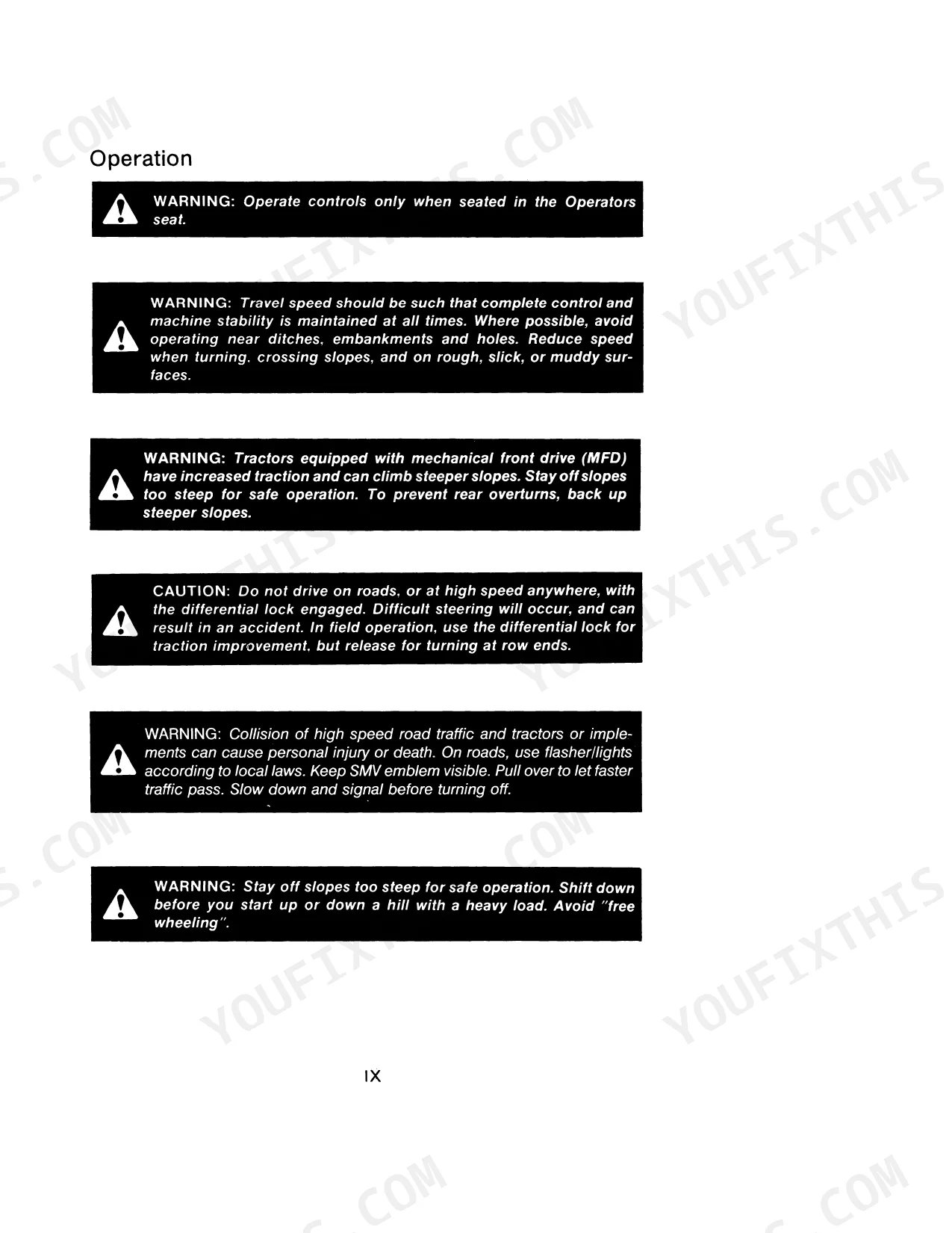
| Safety & Hand Signals | 7-16 | Start Engine, Stop Engine, Move Out, Follow Me, Raise Equipment, Decrease Speed |
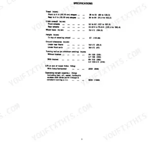
| Specifications | 17-35 | Firing Order, Piston Displacement, Maximum Horsepower, Tractor Brakes, Transmission, Clutch, Turning Radius, Operating Weight, Tire Inflation Specifications, Wheel Mounting Torques, Diesel Fuel Specifications |
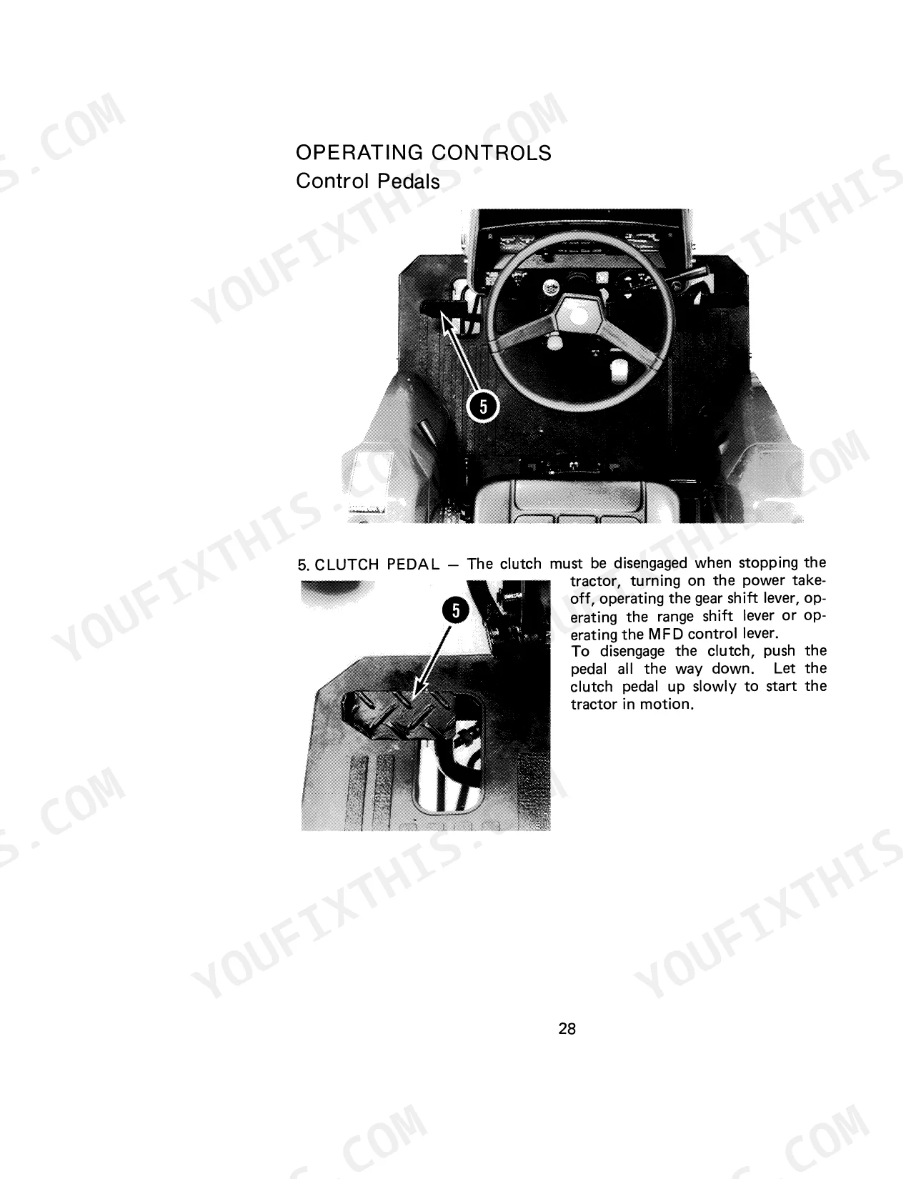
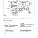
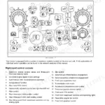
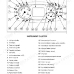
| Controls & Instruments | 36-56 | Tachometer and Hourmeter, Fuel Gauge, Engine Coolant Temperature Gauge, Engine Oil Pressure Indicator, Control Pedals, Control Levers, Operators Seat, Warning Lamps |
| Starting, Operating & ROPS Safety | 57-77 | Run-In Procedure, Towing, Fuel Shut-Off Valve, Starter Key Switch, Emergency Engine Stop Control, Coolant Heater, Seat Belt, Foldable ROPS Frame, Folding the ROPS, ROPS Label |
| Transmission, Differential & PTO | 78-86 | Transmission Operation, Mechanical Front Drive (MFD), Differential Lock, Rear PTO, Mid PTO, PTO Speeds, Live PTO, PTO Safety Guard, Implement Driveline, PTO Shaft |
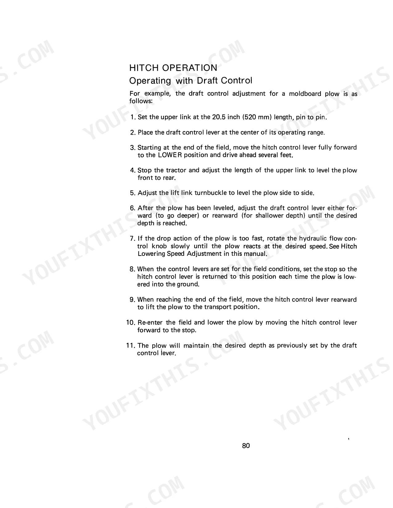
| Drawbar & Three-Point Hitch | 87-97 | Drawbar Hitch, Implement Hitch, Safety Chain, Three Point Hitch, Implement Mast, Lift Link, Upper Link, Stabilizer Chain, Draft Control Lever, Hitch Lowering Speed Adjustment |
| Remote Hydraulics & Wheel/Ballast Adjustments | 98-109 | Remote Hydraulic Control Valve, Hydraulic Adapter Plate, Front Wheel Tread Adjustment, Toe-In Adjustment, Rear Wheel Adjustments, Front End Weights, Rear Wheel Weights, Tire Liquid Weights |
| Lubrication & Preventive Maintenance | 110-129 | Lubrication Points, Approximate Capacities, Engine Oil Level, Engine Oil Change, Engine Oil Filter, Transmission & Hydraulic Lubrication, Front Axle Oil Change, Rear Axle Oil Change, Tire and Rim Repair, Hood Latch |
| Cooling, Fuel & Air Induction Systems | 130-144 | Thermostat Check, Thermostat Replacement, Fan Belt Adjustment, Fuel Filter Element Replacement, Fuel System Air Removal, Fuel Injection Pump and Nozzle Check, Air Filter Element Removal, Dust Container |
| Clutch, Electrical & Battery Service | 145-165 | Clutch Pedal Movement Adjustment, Neutral Start Switch, Head Lamps, Turn Signal and Flasher Lamp, Battery Access, Battery Cables and Terminals, Battery Removal and Installation, Battery Charging |
| Storage & ROPS Maintenance | 166-172 | ROPS Inspection and Maintenance, ROPS Mounting Bolts, Seat Belt Mounting Bolts, Storing the Tractor, Engine Oil, Fuel Tank, Cooling System, Battery, Removing From Storage |
Quick Reference Specifications
| Specification | Value | Page |
|---|---|---|
| Front Wheel Disc to Axle Hub Bolts (2WD) Torque | 61 to 69 lb ft (83 to 93 Nm) | p. 33 |
| Rear Wheel Disc to Axle Hub Bolts Torque | 87 to 97 lb ft (118 to 132 Nm) | p. 33 |
| Rear Wheel Rim to Wheel Disc Nuts Torque | 112 to 127 lb ft (152 to 172 Nm) | p. 33 |
Case IH 275 Common Problems This Manual Covers
Engine coolant temperature gauge climbing toward the red zone during field work
Reduce load immediately and let the engine idle for 2 to 3 minutes before shutdown. Check coolant level at the radiator cap when the engine is cold, per page 130. Clean the grille screen and radiator core of crop debris; restricted airflow is the most frequent cause. Inspect the fan belt for wear or slippage.
Manual Section: Cooling System p. 130Engine cranks but won't start after running the fuel tank dry or replacing the filter
Open the fuel shut-off valve fully, then drain any water from the filter cup on page 138. Follow the air removal procedure on page 138 to bleed the system completely. Verify the diesel grade meets the Number Two Diesel Fuel specification on page 34; an incorrect seasonal blend causes repeated hard-start conditions.
Manual Section: Fuel System p. 138Warning light stays on after startup, charge indicator or oil pressure light not clearing
Identify the indicator using the chart on page 36 before proceeding. If the oil pressure light is on, stop the engine within 30 seconds and check the dipstick level. If the charge light is on, inspect the alternator belt for slippage or breakage. Check fuses on page 153 if the indicator glows but no fault is apparent.
Manual Section: Instruments and Indicators p. 36Rear wheels vibrating or pulling to one side, wheel feels loose under field load
Park on level ground and check wheel disc-to-hub bolt torque on page 33. Rear wheel disc-to-axle hub bolts require 87 to 97 lb ft (118 to 132 Nm); rim-to-disc nuts require 112 to 127 lb ft (152 to 172 Nm). Verify tire inflation falls within the range listed on page 25 for your tire size and load rating.
Manual Section: Wheel Mounting Torques p. 33PTO shaft won't engage at the stub or implement loses power mid-operation
Verify the PTO control lever is fully engaged and the safety guard is installed per page 85. Set engine speed to achieve 540 RPM at the PTO stub; the required engine RPM is listed on page 81. If the PTO slips under load, check clutch pedal free travel and adjustment on page 145 before returning to field operation.
Manual Section: Power Takeoff (PTO) p. 81Frequently Asked Questions
What are the torque specs for engine bolts on Case IH 275?
The manual provides specific torque specifications for certain engine-related bolts. For instance, the drain plug in the oil pan should be tightened to a torque of 37 to 44 lb ft (49 to 59 Nm). Additionally, the bolts for the thermostat replacement require a torque of 12 lb ft (16 Nm), and the adjusting bolt and pivot nut for the fan belt adjustment should be tightened to 13 lb ft (16 Nm). p. 101
How do you fix case IH 275 tractor cranks
Watch the glow plug indicator on page 36 and wait for it to extinguish before operating the starter. Connect the coolant heater as described on page 64 when temperatures drop below freezing. Limit each crank attempt to 30 seconds; wait at least 2 minutes between attempts to protect the starter motor. p. 64
What do I get after purchasing this Case IH 275 Tractor manual?
This is a 172-page searchable PDF (21 MB) ready for immediate download. Works on any device, so pull it up on your phone while you're under the hood. No shipping, no waiting.
Am I able to print pages from this Case IH 275 Tractor manual?
Absolutely. No DRM or copy protection. Print the whole manual or just the pages you need. Any home or office printer works.
Does this Case IH 275 Tractor manual include hydraulic schematics?
Yes. The manual includes a hydraulic system diagram covering the main circuits.


Reviews
There are no reviews yet.