


Part of the John Deere Repair Manuals.
This is the John Deere TM1460 repair manual for the 4555, 4755, 4955, 4560, 4760, and 4960 tractors, all built around the 6076 diesel engine. It is the factory repair volume, 906 pages of the exact remove, inspect, assemble, and torque procedures John Deere wrote for its own service technicians, covering both the 55 Series (Version A) and 60 Series (Version B) machines for the North American and European markets.The manual is organized by system: engine service, fuel and air, electrical repair, the Quad-Range and Power Shift power trains, differential and final drive, steering and brakes, hydraulics, and the operator station. Torque charts, clearances, and specifications open each group.With it you can pull and reinstall the front axle, rebuild a transmission clutch pack, service the hydraulic pump, or trace an electrical fault, working to the correct values instead of guessing. Delivered as an instant PDF download you can read on any device or print.
What's Inside This John Deere 4555–4960 Repair Manual
| System | Pages | Key Topics |
|---|---|---|
| Safety | 9-20 | Group 05, Safety Information, Prevent Machine Runaway, Handle Fluids Safely, Avoid Fires, Prevent Battery Explosions, Prepare for Emergencies, Prevent Acid Burns |
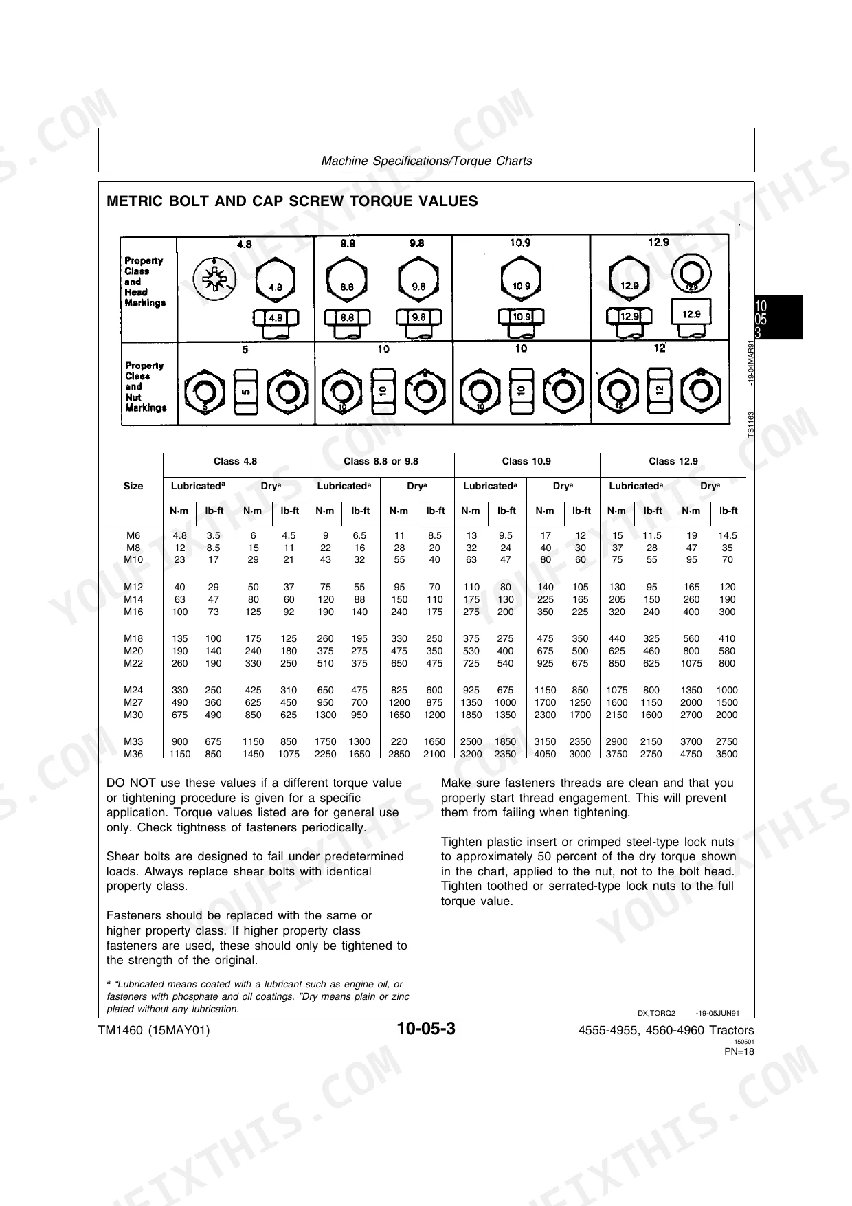
| General Information | 21-38 | Group 05, Machine Specifications (Torque Charts, Metric, English, Abbreviations), Group 10, Predelivery Service (Dealer Predelivery Service, Specifications) |
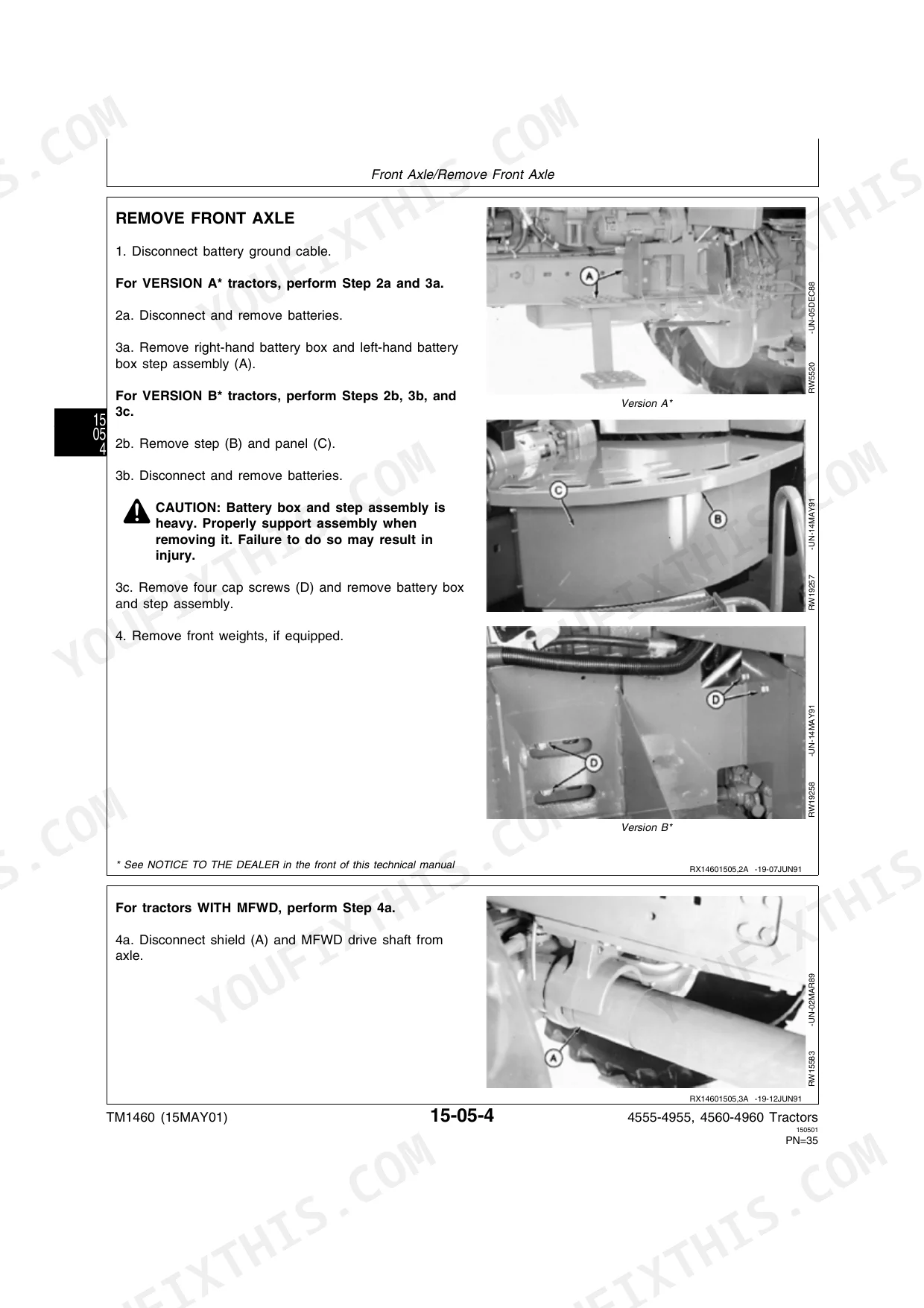
| Separation | 39-128 | Group 05, Front Axle (Special or Essential Tools, Specifications, Front Axle Separation, Remove Front Axle, Install Front Axle) |
| Engine | 129-140 | Group 05, Service (Engine Repair, Remove Injection Nozzles, Valve Cover, Remove and Install) |
| Fuel and Air | 141-148 | Group 05, Air Intake System (Repair Engine, Use CTM6, Remove, Install) |
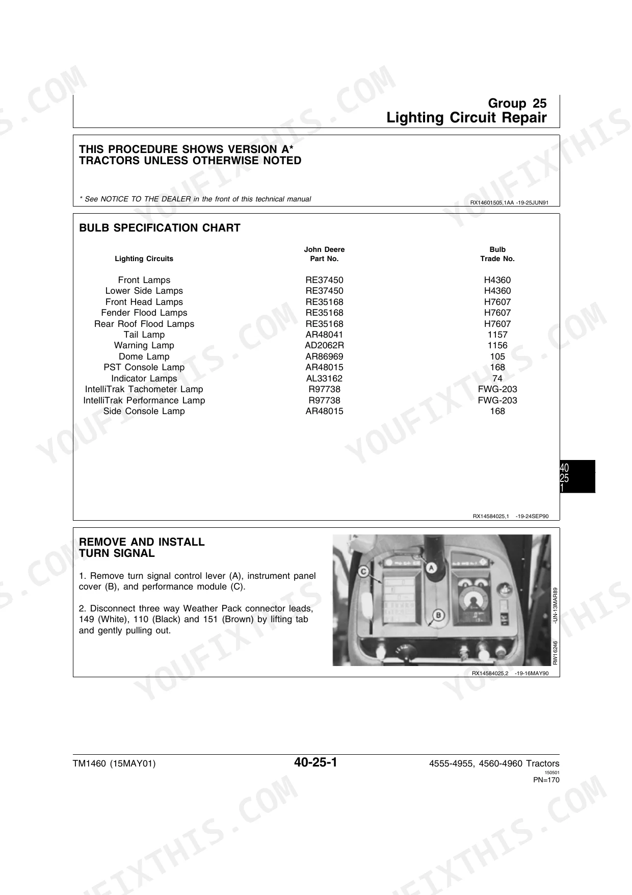
| Electrical Repair | 149-240 | Group 05, Connector Repair (Servicing Equipment and Tools, Remove and Install Batteries) |
| Power Train Quad-Range Transmission | 241-348 | Group 05, Clutch Oil Pressure Regulating Valve Housing (Specifications, Remove and Install, Disassemble, Inspect, And Assemble, Remove, And Install Pressure Regulating Valve, Adjust Clutch Pedal Travel) |
| Power Train Power Shift Transmission | 349-586 | Group 05, Remove and Install Traction Clutch Valve Housing (Specifications) |
| Differential and Final Drive | 587-628 | Group 05, Differential (Special or Essential Tools, Service Equipment and Tools, Other Material, Specifications, Remove, Exploded Views, Disassemble, Inspect, And Assemble, Install, Adjust Differential Preload, Adjust Differential Backlash, Final Assembly of Differential) |
| Steering and Brakes | 629-710 | Group 05, Remove and Install Power Steering Components (Special or Essential Tools, Specifications, Steering Column, Metering Pump, Steering Valve, Steering Motor) |
| Hydraulics | 711-800 | Group 05, Hydraulic System Repair (Avoid High Pressure Fluids, Disconnect Battery Ground, Hydraulic Pump Repair-Use Ctm-7) |
| Miscellaneous | 801-824 | Group 05, Rear Wheels (Special or Essential Tools, Service Equipment and Tools, Specifications, Adjust Rear Drive Wheels, Version a, Version B, Tighten Wheel Sleeve Bolts, Install Dual Wheel Extensions, Adjust Dual Wheels with Extensions) |
| Operator Station Repair | 825-884 | Group 05, Air Conditioning System (Special or Essential Tools, Service Equipment and Tools, Other Material, Service Parts Kits, Specifications, Hose and Tubing Connection Torques, Service Refrigerant Couplings, Discharge Air Conditioning System, Compressor, Remove and Install, Test Volumetric Efficiency, Test Shaft Seal Leakage, Disassemble and Inspect, Replace Clutch Pulley Bearing, Inspect Clutch Pulley, Bearing and Hub, Replace Shaft Seal Seat, Assemble, Inspect Manifolds, Relief Valve, Adjust Belts, Service Other System Components, Hydraulic Oil Cooler/Condenser, Leak Test, Receiver-Dryer, Replace, Evaporator/Heater Core, Remove, Test and Install, Expansion Valve, Service, Test, Service Temperature Control Switch, Clean, And Install Air Filters) |
| Dealer Fabricated Tools | 885-900 | Group 05, Fabricated Tools (DF1064, Ring Gear Puller, DFRW1, Coupler Holding Tool, DFRW7, Differential Lifting Tool, DFRW14, PTO Drive Shaft Rotation Tool, DFRW15, PTO Clutch Support Shaft End Play Tool, DFRW18, Lifting Hook, DFRW20, Compressor Holding Fixture, DFRW29, Final Drive Adapter Housing, DFRW30, Axle Jacking Tool, DFRW32, Lube Tube Removal Tool, DFRW33, Metering Pump Seal Holding Tool, DFRW35, Shock Absorber Spring Compressor, DFRW37, Rockshaft Lift Tool, DFRW48, Differential Drive Shaft Holding Tool, DFRW59, Transmission Input Shaft Removal Tool, DFRW74, Injection Tool Handle, DFRW76, Wheel Installation Pilot) |
Quick Reference Specifications
| Specification | Value | Page |
|---|---|---|
| Front Wheel to Hub (Standard Two-Wheel Drive) | 135 Nm (100 lb-ft) | p. 30 |
| Rear Wheel-To-Rim | 600 Nm (445 lb-ft) | p. 30 |
| Front Axle (Regular/Wide) | 605 Nm (445 lb-ft) | p. 30 |
| Rear Wheel Sleeve Retaining Bolt | 500 Nm (370 lb-ft) | p. 30 |
| Clutch Oil Pressure Regulating Valve Housing-to-Transmission Case | 48 Nm (35 lb-ft) | p. 243 |
| PTO Clutch Backing Plate-to-Drive Gear Cap Screw | 54 Nm (40 lb-ft) | p. 493 |
| Clutch Housing-to-Engine | 406 Nm (300 lb-ft) | p. 64 |
| Side Frame-to-Engine (12 Point Cap Screws) | 578 Nm (426 lb-ft) | p. 61 |
| Recommended Transmission/Hydraulic Oil | John Deere HY-GARD® Transmission/Hydraulic Oil or QUATROL® oils or oils meeting John Deere Standard JDM J20A or J20B | p. 35 |
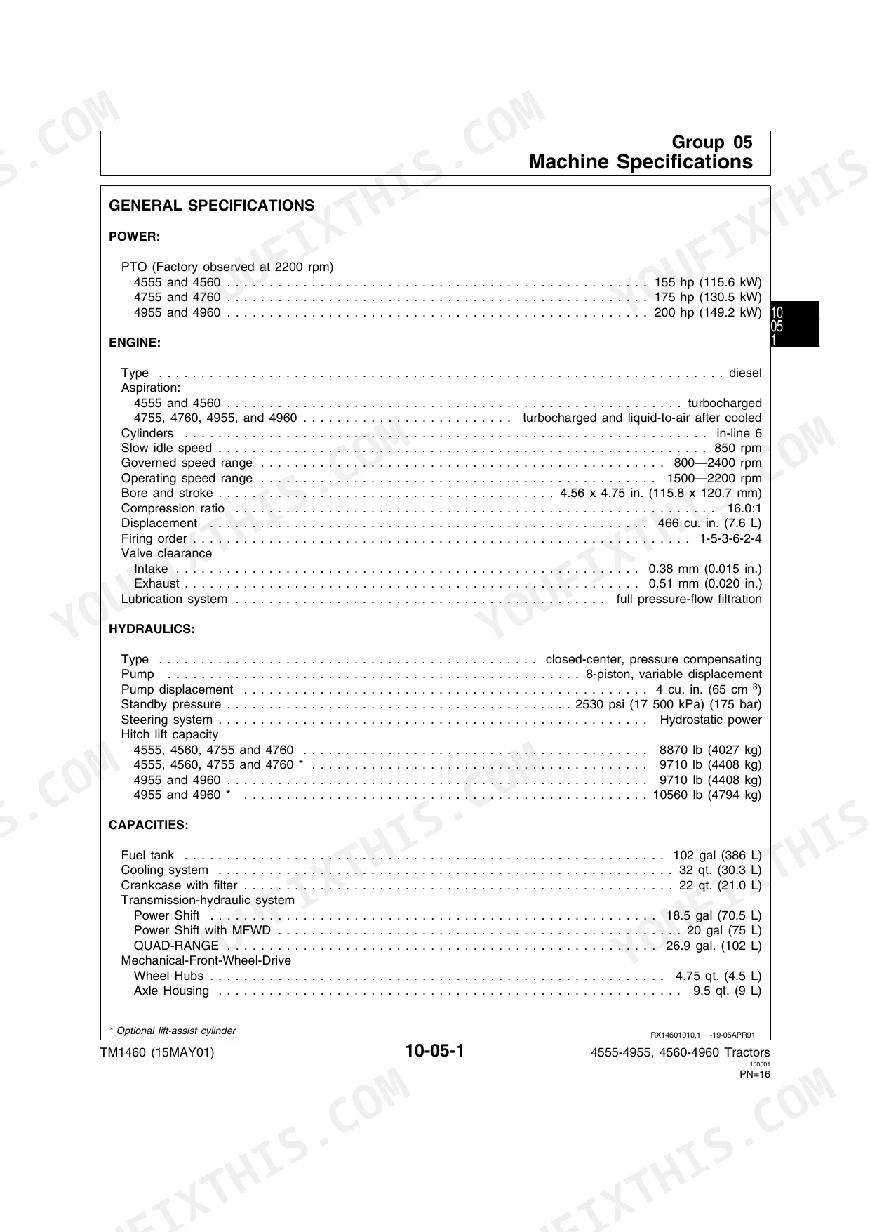
| Pump displacement | 4 cu. in. (65 cm3) | p. 23 |
| Main Hydraulic Pump Standby Pressure (Deadhead) | 17 200–17 800 kPa (172–178 bar) (2495–2580 psi) | p. 716 |
| Traction Clutch Valve Housing Cap Screws Torque | 48 Nm (35 lb-ft) | p. 353 |
John Deere 4555–4960 Common Problems This Manual Covers
Slipping gears or loss of drive
Owners report the Power Shift transmission slipping, dropping drive, or failing to move under load, often from internal clutch wear or control issues. Early 15-speed Power Shift units were known for problems that later service actions addressed. The Power Shift transmission section gives the remove, disassemble, inspect, and reassemble procedures with clutch specs.
Manual Section: Power Train Power Shift Transmission p. 349Weak lift or no hydraulic response
A tired hydraulic pump, sticking valve, or contaminated fluid shows up as slow implement lift, erratic function, or no response at all. The Hydraulics section walks through pump repair and system pressure checks so you can confirm standby pressure before condemning parts.
Manual Section: Hydraulics p. 711Hard starting or rough running
Hard starts, rough idle, and power loss on these tractors usually trace back to the fuel and air side: air in the fuel, injection nozzle wear, or a restricted intake. The Fuel And Air section covers the air intake system and injection nozzle service.
Manual Section: Fuel And Air p. 141Electrical faults and no-start
Intermittent gauges, dead lighting, and starting circuit failures often come down to grounds, switches, relays, or a damaged harness. The Electrical Repair section covers connector repair and battery removal and installation to help isolate the fault.
Manual Section: Electrical Repair p. 149Heavy or delayed steering
Steering that feels heavy, delayed, or inconsistent points to power steering wear, low fluid, or a metering pump or steering valve problem. The Steering And Brakes section covers removal and installation of the steering column, metering pump, steering valve, and motor.
Manual Section: Steering And Brakes p. 629Differential noise or drivetrain wear
Whine, backlash, or play in the final drive means the differential needs inspection and preload adjustment. The Differential And Final Drive section provides the exploded views, wear specs, and the differential preload and backlash adjustment procedures.
Manual Section: Differential And Final Drive p. 587Frequently Asked Questions
Which tractors does this manual cover?
It covers the John Deere 4555, 4755, 4955, 4560, 4760, and 4960 tractors, all using the 6076 engine. It is the TM1460 repair manual and covers both Version A (55 Series) and Version B (60 Series) machines for North America, plus the European-market 4755 and 4955.
What torque values does it include?
The General Information section opens with machine specifications and torque charts in both metric and English units, plus predelivery service values such as the rear wheel-to-rim torque of 600 Nm (445 lb-ft). Individual sections repeat the torque specs for the parts they cover. p. 21
What is the hydraulic pump standby pressure?
The Hydraulics section lists the main hydraulic pump standby (deadhead) pressure as 17 200 to 17 800 kPa (172 to 178 bar, 2495 to 2580 psi). The same section covers hydraulic pump repair and the pump-to-support torque of 116 Nm (85 lb-ft). p. 711
Is this the real factory manual or an aftermarket guide?
It is the genuine John Deere factory repair manual, TM1460 from John Deere Waterloo Works, the same document dealer technicians use. It contains repair procedures; for diagnostics and tests John Deere pairs it with the separate TM1461 volume.
Is this John Deere 4555 & variants Repair Manual a digital download?
Instant PDF download. You get the full 906-page searchable Repair Manual immediately after payment. Open it on your laptop, tablet, or phone right in the shop.
Is this John Deere 4555 & variants Repair Manual printable?
Yes. The PDF has no DRM restrictions, print any page or section you need for your shop. Works with any standard printer.


Reviews
There are no reviews yet.